Myron L 729II User Manual
Page 51
47
For Conductivity/TDS - X1, X10 and X100.
For Resistivity - X1, 0.1, and 0.01.
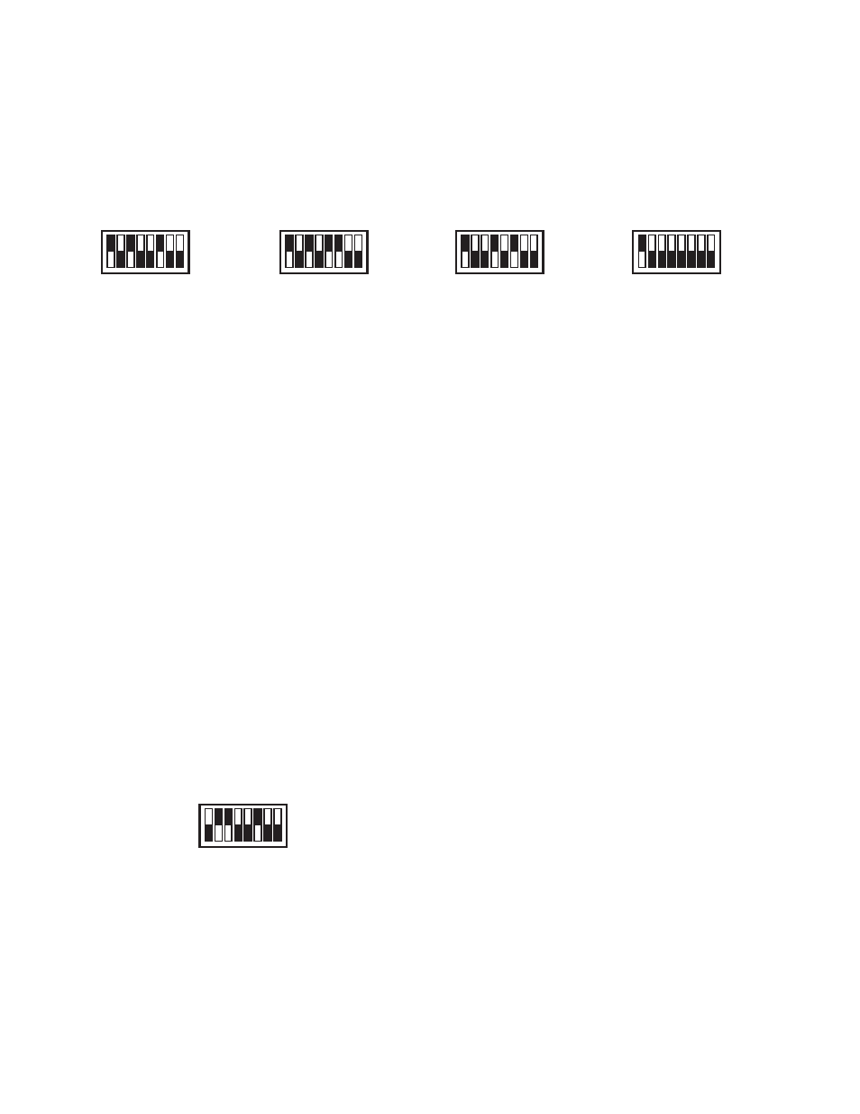
If adding an alarm/control range.
1. Locate the 8 position select switch on the 3SR Module.
2. Set appropriate select switch UP or ON, i.e. to add
X100, set switch marked X100 UP or ON, see
figure III.H.7.
If changing alarm/control from one range to another, i.e. X1 to
X10 Range.
1. Locate the 8 position select switch on the 3SR Module.
2. Set the X1 select switch in the DOWN or OFF position.
3. Set the X10 select switch in the UP or ON position, see
figure III.H.8.
To disable either COND/TDS or Resistivity alarm/control
function completely.
1. Locate the 8 position select switch on the 3SR Module.
2. Set all X prefixed and S prefixed select switches in the
DOWN or OFF position, see figure III.H.9.
To reconfigure Conductivity to Resistivity or vise versa.
If you have a Resistivity Monitor/controller and ordered a 3SRO
Module as an accessory you may need to reconfigure the select
switch for it to Range properly.
1. Locate the 8 position select switch on the 3SR Module.
2. Set the COND select switch in the DOWN or
OFF position, see figure III.H.10.
3. Set the RES select switch in the UP or ON position,
see figure III.H.10.
Naturally, if you have a 3SR Module configured for a Resistivity
Monitor/controller and desire it to be for a Conductivity Monitor/
controller, reverse #2 & 3 above.
REASSEMBLY:
1. Carefully reinstall the front panel, bottom first. Ensure
no wires have been pinched between enclosure and
front panel.
2. Reinstall the four (4) screws and tighten.
3. To operate, turn power ON.
Figure III.H.6
Figure III.H.8
Figure III.H.7
Figure III.H.9
Factory Default
ON
ON
ON
COND RES X1 X10 X100 S1 S2 S3
COND RES X1 X10 X100 S1 S2 S3
COND RES X1 X10 X100 S1 S2 S3
COND RES X1 X10 X100 S1 S2 S3
ON
COND RES X1 X10 X100 S1 S2 S3
Figure III.H.10
ON