General specifications – Vaddio WallVIEW CCU Kit for AW HE-120 User Manual
Page 11
Quick Connect CCU Kit and WallVIEW Kit for the AW-HE120
© 2012 Vaddio - All Rights Reserved. Document Number 342-0498 Rev A Page 11 of 16
Adjust the Y Gain Settings*: Enable both Auto Iris and Auto White Balance prior to adjustment. Make sure
the distance adjustment is set at its lowest setting. Adjust the trim pot on the back of the CCU counter-
clockwise until picture fades or drops out (cable length dependent). Adjust clockwise just past the setting
where picture is restored. Leave the distance adjustment** at its lowest setting unless recommended by
Vaddio technical support.
Adjust Iris and Digital Gain Settings: Disable Auto Iris. Set the Iris to its largest aperture (lowest ‘f’
number). Adjust the Gain until the image is too dark and then bring it back until it is properly exposed.
Exposures that require high gain settings will have a grainy video image. Adjust the detail settings for a
smoother image.
Adjust Color to Taste: Required adjustments will vary based on the environment. The CCU allows the set-
up of several scenes so settings are available for a variety of conditions. Adjust the Chroma level to taste.
Adjust Red/Blue levels next. Adjusting for skin tones or using a color chart is an easy way to find a good
baseline setup.
*Y Gain adjustment not active on CCU when using the SDI option
**Distance adjustment not active on CCU when using the SDI option
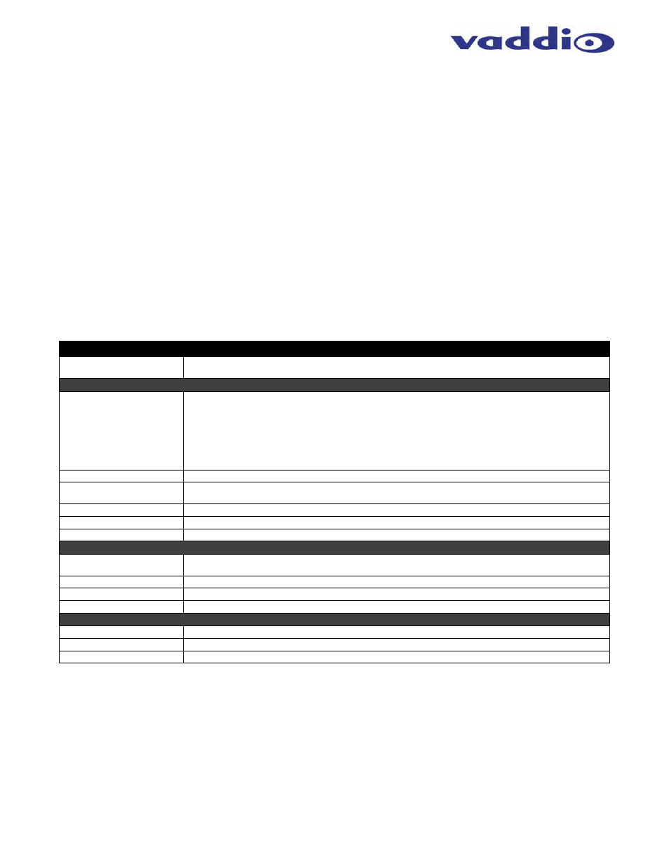
General Specifications
Quick-Connect CCU HE120 (Please see specs for Panasonic camera in the Panasonic manual)
Part Numbers
998-
6897-
000: Quick-Connect CCU Kit for the BRC-H900 Camera (camera not included) - North America
999-
6897
-001: Quick-Connect CCU Kit for the BRC-H900 Camera (camera not included) - International
Quick-Connect CCU Interface
Connectors
Power Connector: 5.5mm OD x 2.5mm ID
Power RJ-45: Supplies 36V to EZCamera Interface Module Regulator
Control In RJ-45: Accepts RS-232 from ProductionVIEW or other non-daisy-chain control systems
Control Out RJ-45: Passes RS-232 and Sync video feed to camera EZIM
Tally: 2-Pin Phoenix type spring cage connector
Video Inputs: BNC Connector for Sync
Video Outputs: BNC Connectors for HD Analog Component (Y,PB,PR) / SD (Composite)
Video RJ-45: Transports HD video from camera EZIM
Camera Select Switch
For Future Use – All switches should be in the down position
Video Adjustments
Y-Gain (luminance gain) for fine tuning over longer cable distances
Distance Compensation: 100’, 200’, 300’, 400’+
CAT-5 Cable Distance
Up to 500’ (152.4m)
Power Supply
36 VDC, 2.78 Amp
Dimensions
1-RU Rack Mount - 1.75” H x 19” W x 6” D (4.45 cm x 4.26 cm x 15.24 cm)
EZCamera Interface Module CCU (EZIM)
Connectors
Three (3) RJ-45 Connectors
One DB-25 for Power, Video, Control & Genlock
Cable Assembly
DB-25M to DE-15, DE-9, BNC x 2, 3mm ID Power Connector
Power Regulator
Supplies 12VDC to Cameras
Dimensions
3” H x 4.5” W x 1.2” D (7.6 cm x 11.4 cm x 3 cm)
Wall Mount H900 P/N: 535-2000-225
Materials
12-Gauge CRS with Black Powder Coat Paint
Dimensions
8” H x 8.5” W x 13.5” D (20.3 cm x 21.6 cm x 34.3 cm)
Weight
Approx. 6 lbs. (2.7kg)