Optimizing system performance – Vaddio WallVIEW CCU Kit for AW HE-120 User Manual
Page 10
Quick Connect CCU Kit and WallVIEW Kit for the AW-HE120
© 2012 Vaddio - All Rights Reserved. Document Number 342-0498 Rev A Page 10 of 16
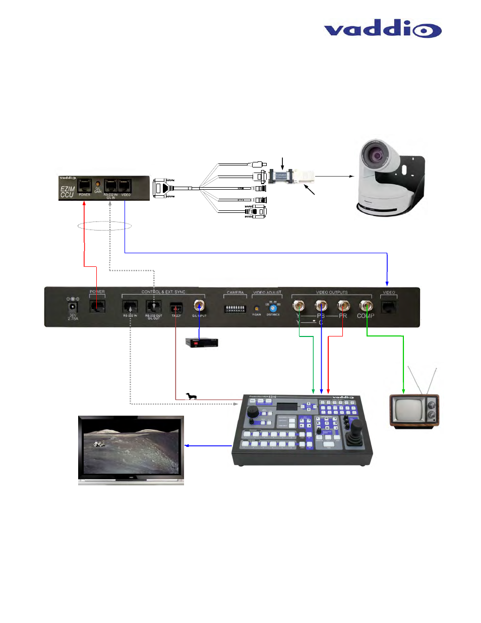
Drawing: Basic System Connectivity
Wiring Diagram Example:
System Configuration Notes:
The Quick-Connect CCU System uses a Cat-5 (all 4-pairs) for power to ensure the motors receive the required current to operate properly.
The Video Cat-5 cable uses all four pairs for video (YPbPr & CVBS). The RS-232 Cat-5 provides communication to the camera for CCU, PTZ
control and G/L (where applicable) to the camera. These Cat. 5 cables can be run up to 500’ (152.4m). See Appendix 1 for wiring and pin-
out information.
Optimizing System Performance:
Optimizing the CCU settings will help achieve maximum performance from the system. Difficult lighting is one of
the most challenging problems video system integrators face. The Vaddio CCU will provide the flexibility to fine
tune for variables such as cable length, day/night lighting transitions and lighting color temperature.
CCU Control Mode: CCU’s that are sold with cameras other than Vaddio will have a CCU Control button
with the scene controls. Make sure and select CCU Control if available prior to making CCU adjustments.
PTZ control will not be available in this mode.
Cat-5 Cables
up to 500’
HD Break-out
Cable
EZIM CCU Top Panel
Power
RS-232 & G/L
HSDS Video on Cat-5
RS-232
Tally
ProductionVIEW HD
HD-YPbPr Out
Quick-Connect CCU
AW-HE120 Camera, Wall Mount
with EZIM CCU (behind camera)
Note: Camera not included
HD YPbPr
+
G
Composite
Video
Simulated Video Feed
HD Video
G/L Box
RS- 232 to
RS-422
Converter
Power
G/L
CVBS
RS-422
on 1 ft.
Cat.-5
DB-9 F
to Cat 5