Installation – Pulsafeeder Chem-Tech Series XP TIMER EN User Manual
Page 5
REV. A PN J63143
- 5 -
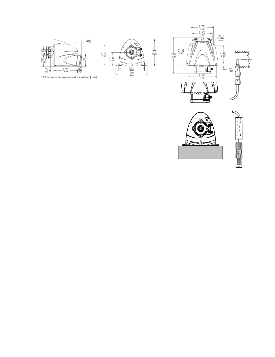
Figure 2: Injector Placement
Vertical
Mount
Horizontal
Figure 1: Pump Dimensions
4. Installation
NOTE: For pumps operating in swimming pool
installations the pump is to be supplied by an isolating
transformer or through a residual current device (RCD).
1) The pump can be installed either vertically or
horizontally (See Figure 2). Make sure to secure the
pump on a flat level surface that will support 50-lbs
(22kg) and secure with four .25-in (6mm) screws in the
holes provided. The guard snaps into the back of the
pump via three tangs -- see Figure 1. The pump
should be mounted with no less than 1.75-in
(44mm) of clearance around the venting on both
the front and the rear of the pump. Locate the
pump so there is direct access to the power cord plug.
The pump is rated for indoor use only. For applications that are subject to
splashing, make sure the pump is mounted horizontally level with splash guard in
place. Vertical mountings require the purchase of optional hood (J63004).
Select a location that does not subject the timers LCD to direct sunlight.
2) Verify the electrical requirements for the pump as listed on the name plate
and connect to an appropriate electrical source in compliance with local codes for
the specific application.
3) Relieve the system pressure and drain the piping run where the injection
fitting is to be installed. See Figure 2 for reference. The injection fitting must
not be installed in a dead end pipe or a deeply recessed tee. It should be
installed so as to place the tip at the center of the fluid stream as indicated
in Figure 2. The injection fitting is supplied with .25-in NPT threads. If necessary
drill a .44-in (11mm) diameter hole and using care not to tap to deeply, tap for
.25-in NPT.