Pulsafeeder Chem-Tech Series XP TIMER EN User Manual
Page 14
REV. A PN J63143
- 14 -
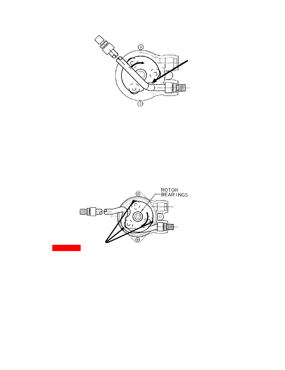
Figure 9a: Rotor Alignment at Start of Tube Installation
3) Insert one connector end of the tubing assembly into the bottom retaining slot
in the pump head. Insert the tube through the guide slot in the rotor. Using
caution, intermittently jog the mode selector switch to from the on and off
positions and feed the tube around the pump head as the guide slot rotates. Be
very careful not to get any objects (fingers, ties, hair, etc.) close to the
rotors and pump head as severe pinch points exist, see Figure 9b. Keep
hands and fingers away from the rotor assembly while feeding the new
tube.
Figure 9b: Feeding the New Tube
When the rotor is positioned as in Figure 9c, set the mode selector switch all the
way to the right into the off position. Insert the other connector into its retaining
slot.
4) Align the pump head cover bearing bore with the rotor shaft and press into
place.
5) Loosely reinstall the two thumb screws.
Note position of tube and
rotor’s cut-away guide
slot.
WARNING:
Note severe pinch points between rollers and pump housing