Filter, Final steps, Operation – COOK H-Series User Manual
Page 4: Inspection, Final installation steps, Rotating parts & electrical shock hazard
4
c. Install the two perimeter angles (C), that were shipped
loose, inside each end of the hood.
d. If there is a gap between the top cap edges, loosen the
top cap bolts. Install a bolt in each end of the top cap
flange to pull the two top caps together. Tighten the top
cap bolts.
Filtered Fans
a. Place the two long filter retainers (E) --four on size 60--
and the two short filter retainers (F) on top of the base
and bolt the pieces together.
b. Bolt the long filter retainers (E) to the perimeter angles
(C) that are at the ends of each hood.
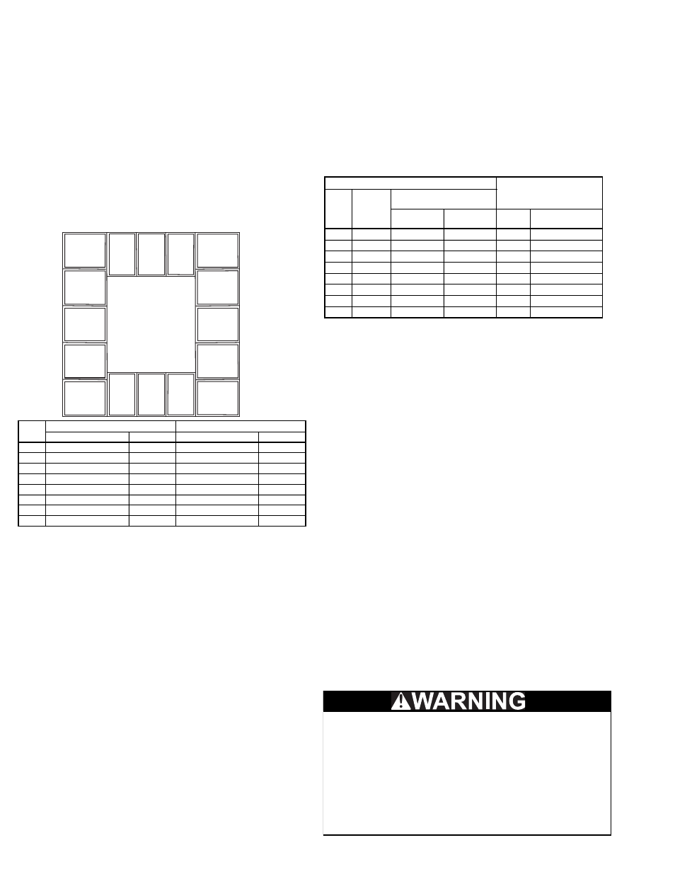
c. Install filters according to the filter schedule. Refer to Fil-
ter Installation Detail, below. Insert edge of filters into the
filter retainer (E), swing filter into position and flip the fil-
ter holding clip into position.
Final Installation Steps
a. Inspect fasteners and setscrews, particularly fan
mounting and bearing fasteners, and tighten according
to the recommended torque shown in the table, Rec-
ommended Torque for Setscrews/Bolts.
b. Inspect for correct voltage with voltmeter.
c. Ensure all accessories are installed.
d. Test the fan to be sure the rotation is the same as indi-
cated by the arrow marked Rotation.
Do not allow the fan to run in the wrong direction.
This will overheat the motor and cause serious dam-
age. For 3-phase motors, if the fan is running in the
wrong direction, check the control switch. It is possible
to interchange two leads at this location so that the fan
is operating in the correct direction.
Operation
Pre-Start Checks
a. Lock out all the primary and secondary power sources.
b. Inspect fasteners and setscrews, particularly those
used for mounting the fan, and tighten if necessary.
c. Inspect belt tension and pulley alignment. (Remember,
if belt tension is correct, a loud squeal occurs as the fan
increases to full power.)
Unit
Type 1
Type 2
Size
Length x Width
No. Req’d
Length x Width
No. Req’d
20
14 x 14”
4
14 x 18-7/8”
6
24
18-1/4” x 30-1/8”
2
18-1/4” x 33-1/4”
4
30
20-7/16” x 18-1/16”
4
20-7/16” x 25-13/16”
6
36
22-1/4” x 21-1/16”
4
22-1/4” x 29-5/32
6
42
24-1/16” x 29-1/2”
4
26-7/8” x 19-1/4”
8
48
27” x 27”
4
27” x 27
8
54
29-1/8” x 20”
6
29-1/8” x 23-5/8”
10
60
37-11/16” x 21-7/8
6
26” x 28-5/16”
10
Filter
Schedule
Type 2
Type 2
Type 2
Type 2
Type 2
Type 2
Type 2
Type 2
Type 2
Type 2
T
ype 1
T
ype 1
T
ype 1
T
ype
1
T
ype 1
T
ype 1
d. Inspect motor wiring.
e. Ensure the belt touches only the pulleys.
f. Rotate the propeller to ensure it does not rub against
the venturi.
g. Ensure fan and ductwork are clean and free of debris.
h. Test the fan to ensure the rotation of the propeller is
the same as indicated by the rotation label (The HER
has a reversible propeller and can be operated in either
direction).
i. Close and secure all access doors.
j. Restore power to unit.
Start Up
Turn the fan on. In variable speed fans, set the fan to its
lowest speed. Inspect for the following:
• Direction of rotation.
• Excessive vibration.
• Unusual noise.
• Bearing noise.
• Improper belt alignment or tension (listen for a continu-
ous squealing noise).
• Improper motor amperage or voltage.
NOTICE! If a problem is discovered, immediately
shut off the fan. Lock out all electrical power and check
for the cause of the trouble. Refer to Troubleshooting.
Inspection
Inspection of the fan should be conducted at the first 30
minute, 8 hour and 24 hour intervals of satisfactory opera-
tion. During the inspections, stop the fan and inspect as per
the chart below.
30 Minute Interval
Inspect bolts, setscrews, and motor mounting bolts.
Adjust and tighten as necessary.
8 Hour Interval
Inspect belt alignment and tension. Adjust and tighten as
necessary.
24 Hour Interval
Inspect belt tension. Adjust and tighten as necessary.
Recommended Torque for Setscrews/Bolts (IN/LB.)
Setscrews
Hold Down Bolts
Size
Key Hex
Across
Flats
Recommended Torque
Inch-lbs.
Min.
Max.
Size
Wrench Torque
(inch-lbs)
No.10
3/32”
28
33
3/8”-16
240
1/4”
1/8”
66
80
1/2”-13
600
5/16”
5/32”
126
156
5/8”-11
1200
3/8”
3/16”
228
275
3/4”-10
2100
7/16”
7/32”
348
384
7/8”-9
2040
1/2”
1/4”
504
600
1”-8
3000
5/8”
5/16”
1104
1200
1-1/8”-7
4200
3/4”
3/8”
1440
1800
1-1/4”-7
6000
Rotating Parts & Electrical Shock Hazard:
Disconnect power before checking and cleaning
filters.
Inadvertent operation of the fan could pull objects
from the roof into the propeller.
Failure to follow these instructions could result in
death or serious injury.