Installation, Wiring diagrams, Damper – COOK H-Series User Manual
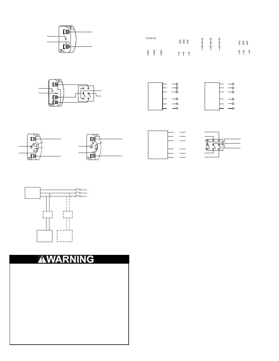
Page 2: Motor, 3 phase, 9 lead motor delta-connection, Single speed, single phase motor, Typical damper motor schematic
2
4 5 6
1
7
2
8
3
9
L1 L2 L3
4 5 6
7 8 9
1 2
3
L1 L2 L3
Low Voltage
208/230 Volts
High Voltage
460 Volts
3 Phase, 9 Lead Motor
Y-Connection
Fan
Motor
Damper
Motor*
Second
Damper
Motor
Transformer**
Transformer**
L3
L2
L1
7
1
6
7 8 9
4 5 6
1 2
3
Low Voltage
208/230 Volts
High Voltage
460 Volts
8
2
4
9
3
5
L1
L3
L2
L1
L3
L2
3 Phase, 9 Lead Motor
Delta-Connection
Wiring Diagrams
Wiring Diagrams
When ground is required, attach to ground A or B with no. 6 thread forming
screw. To reverse, interchange T-1 and T-4.
Ground A
L
1
L
2
Line
T-1
T-4
Ground B
Single Speed, Single Phase Motor
To reverse, interchange any 2 line leads.
When ground required, attach to ground A or B with No. 6 thread forming
screw. To reverse, interchange T-1 and T-4 leads.
T-1
T-4
Ground B
Ground A
High Speed
Low Speed
L
1
L
2
Line
2 Speed, 2 Winding, Single Phase Motor
2 Speed, 1 Winding, 3 Phase Motor
To reverse, interchange any 2 line leads. Motors require magnetic control.
Together
Open
Low Speed
High Speed
Motor
Motor
1
2
3
4
5
6
L
1
L
2
L
3
L
1
L
2
L
3
1
2
3
4
5
6
Single Speed, Single Phase, Dual Voltage
2 Speed, 2 Winding, 3 Phase
When ground required, attach to ground A or B with No. 6 thread forming
screw. To reverse, interchange T-5 and J-10 leads.
Link A
Low Voltage
Ground A
Ground B
T-5
J-10
L
1
L
2
Line
T-5
J-10
Ground A
Ground B
Link A & B
High Voltage
L
1
L
2
Line
Link B
To reverse: High Speed-interchange leads T
11
and T
12
.
Low Speed-interchange leads T
1
and T
2
. Both Speeds-interchange any 2
line leads.
T
3
T
2
T
1
T
11
T
12
T
13
Low Speed
Low Speed
Low Speed
High Speed
High Speed
High Speed
L
1
L
2
L
3
Motor
Typical Damper Motor Schematic
For 3 phase, damper motor voltage should be the same between L
1
and
L
2
. For single phase application, disregard L
3
. *Damper motors may be
available in 115, 230 and 460 volt models. The damper motor nameplate
voltage should be verified prior to connection. **A transformer may be pro-
vided in some installations to correct the damper motor voltage to the
specified voltage.
Line
Line
Line
Damper Installation
If your fan is supplied with dampers, follow the directions
below. If your fan does not include dampers, proceed to
Motor Installation.
a. Place the damper inside the curb. Ensure the damper
will open freely for the correct direction of the airflow.
b. Secure to curb at the damper shelf.
c. Drill a hole in the curb shelf for conduit needed for
motor wiring.
d. Operate the dampers manually to ensure the blades
move freely. Dampers should be released from full
open position to check for proper closing.
Motor Installation
If your fan is a direct drive (model HEE-D, HES-D, HEF-D
or HER-D), proceed to Wiring Installation.
To prevent damage to the fan during shipping, motors 5
HP and larger, and extremely heavy motors (cast iron or
severe duty) are shipped loose and must be field mounted.
Installation
The attachment of roof mounted fans to the roof curb
as well as the attachment of roof curbs to the building
structure must exceed the structural requirements
based on the environmental loading derived from the
applicable building code for the site. The local code
official may require variations from the recognized
code based on local data. The licensed engineer of
record will be responsible for prescribing the correct
attachment based on construction materials, code
requirements and environmental effects specific to
the installation.
Failure to follow these instructions could result in
death or serious injury.