Replacing pulleys and belts, Pulley alignment, Bearing replacement – COOK FCRU User Manual
Page 5
5
Replacing Pulleys and Belts
1. Clean the motor and fan shafts.
2. Loosen the motor plate mounting bolts to relieve the belt
tension. Remove the belt.
3. Loosen the pulley setscrews and remove the pulleys
from the shaft. If excessive force is required to remove
the pulleys, a three-jaw puller can be used. This tool,
however, can easily warp a pulley. If the puller is used,
inspect the trueness of the pulley after it is removed
from the shaft. The pulley will need replacement if it is
more than 0.020 inch out of true.
4. Clean the bores of the pulleys and place a light coat of
oil on the bores.
5. Remove any grease, rust or burrs from pulleys.
6. Place the fan pulley on the fan shaft and the motor
pulley on the motor shaft. Damage to the pulleys can
occur when excessive force is used in placing the
pulleys on their respective shafts.
7. After the pulleys have been correctly placed back onto
their shafts, tighten the pulley setscrews.
Belt and Pulley Installation:
Belt tension is determined by the sound of the belts when
the fan is first started. The belts will produce a loud squeal,
which dissipates after the fan is operating at full capacity. If
belt tension is too tight or too loose, lost efficiency and
damage may occur.
Do not change the pulley pitch diameter to change tension.
The change will result in a different fan speed.
1. Loosen motor plate adjustment bolts and slide motor
plate so that belts easily slip into the grooves on the
pulleys. Never pry, roll, or force the belts over the rim of
the pulley.
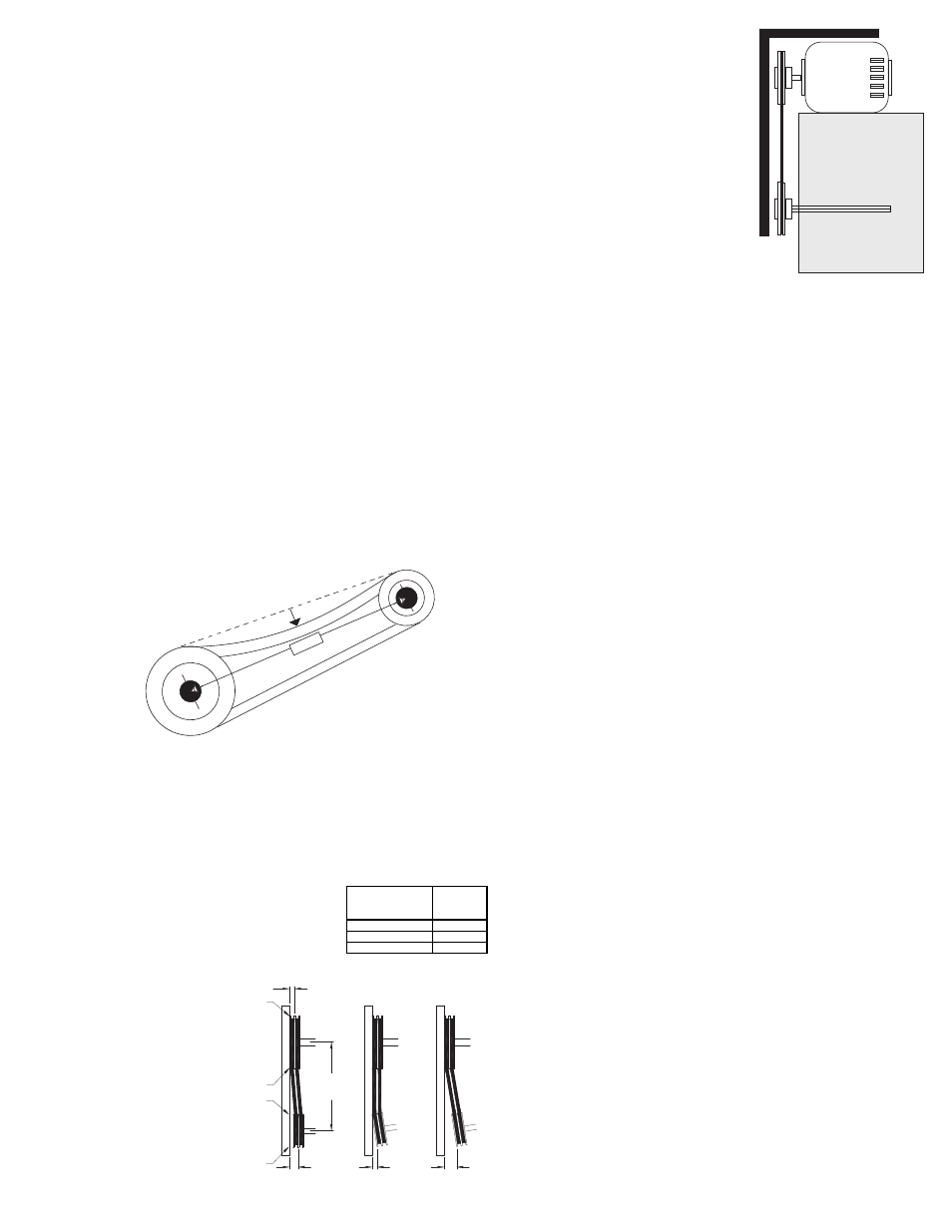
2. Slide motor plate until proper tension is reached. For
proper tension, a deflection of approximately 1/4” per
foot of center
distance should
be obtained by
firmly pressing
the belt. Refer to
Figure 1.
3. Lock the motor
plate adjustment
bolts in place.
4. Ensure pulleys
are properly
aligned. Refer to
Figure 2.
1 foot
1/4 inch
Figure 1
OFFSET
ANGULAR
OFFSET/ANGULAR
A
W
X
Y
Z
B
CENTER
DISTANCE
(CD)
GAP
GAP
Center Distance
Maximum
Gap
Up thru 12”
1/16”
12 through 48”
1/8”
Over 48”
1/4”
Figure 2
Tolerance
Pulley Alignment
Pulley alignment is adjusted by
loosening the motor pulley
setscrew and by moving the motor
pulley on the motor shaft.
Figure 2 indicates where to
measure the allowable gap for the
drive alignment tolerance. All
contact points (indicated by WXYZ)
are to have a gap less than the
tolerance shown in the table. When
the pulleys are not the same width,
the allowable gap must be adjusted
by half of the difference in width. Figure 3 illustrates using a
carpenter’s square to adjust the position of the motor pulley
until the belt is parallel to the longer leg of the square.
Bearing Replacement
The fan bearings are pillow block type ball bearings.
1. Follow all local lock-out / tag-out procedures, remove
topcap from unit and unwire the units motor.
2. Loosen the bolts holding the motor and remove the belt.
Inspect the belt for signs of wear and set aside.
3. While supporting the motor, either by the lifting eye or
around the base on the motor, loosen and remove all
the bolts holding the motor. Do not lift motor by its shaft.
Caution: Motors with cast frames can be extremely
heavy and should not be lifted without additional aid.
Set motor aside.
4. Locate the 4 to 8 bolts on the flat surface of the interior
of the housing. Begin to loosen these bolts and save
the hardware. Note unit may shift during this process.
5. Using the lifting points on the power assembly carefully
lift the assembly straight up until the wheel clears all
parts of the unit. Set the wheel / shaft / power assembly
down in a manner that does not damage the roof or any
component.
6. Measure and record the distance of the wheel from the
support plate.
7. Using a putty knife at the wheel hub, scrape the resin
from the safety plate and retaining bolt.
8. Remove the retaining bolt and safety plate and set
aside.
9. Using either a jewelry screw driver or small drill bit,
remove the beeswax from the set screw openings and
set screw heads.
10. Remove the wheel and remove the old bearings and
shaft.
11. Install the new shaft to the wheel, safety plate, and
retaining bolt. Tighten all per the torque values as
stated on page 2.
12. Using a fiberglass resin repair kit, apply resin per the
manufacture instruction over the safety plate, and
retaining bolt. Recommend using a Grainger part
number 3RAR9 or equal.
13. Reapply beeswax to protect the set screw heads.
14. Install the new shaft by sliding the bearings to the
desired location using the measurement record earlier
and loosely mounting the bearing support. Bearing bolts
and bearing set screws should be loose enough to allow
Figure 3