Damper installation, Wiring installation, Final installation steps – COOK FCRU User Manual
Page 2
2
Damper Installation
If your fan is supplied with dampers, follow the directions
below. If your fan does not include dampers, proceed to
Belt and Pulley Installation.
1. Place the damper inside the curb or inside the duct
work. Ensure the damper will open freely for the correct
direction of the airflow.
2. Secure to curb at the damper shelf.
3. Drill hole in the curb shelf for conduit needed for motor
wiring.
4. Operate the dampers manually to ensure the blades
move freely.
5. Install fan over curb while aligning the conduit location
with the conduit hole in the curb.
Wiring Installation
NOTICE! All wiring should be in accordance
with local ordinances and the National Electrical
Code, NFPA 70. Ensure the power supply
(voltage, frequency, and current carrying
capacity of wires) is in accordance with the
motor nameplate. (See page 3 for diagram)
NOTICE! Fan must be grounded to prevent electrical
discharge.
For Units Without A Junction Box:
An approved metal field wiring compartment must be
secured to the unit with two screws in order that the box
does not rotate. All wires must be protected from abrasion
where they enter and exit the wiring compartment. The
green ground wire from the motor must be secured under
the green ground screws inside the field wiring compartment
using a closed loop connector. Complete connections in
accordance with the wiring diagram on the motor.
For Units With A Junction Box:
Pull wires through the appropriate conduit. Protect wires
from abrasion where they enter the field wiring compartment
and complete connections in accordance with the diagram
on the motor.
Leave enough slack in the wiring to allow for motor
movement when adjusting belt tension. Some fractional
The attachment of roof mounted fans to the roof curb
as well as the attachment of roof curbs to the building
structure must exceed the structural requirements
based on the environmental loading derived from the
applicable building code for the site. The local code
official may require variations from the recognized
code based on local data. The licensed engineer of
record will be responsible for prescribing the correct
attachment based on construction materials, code
requirements and environmental effects specific to
the installation.
Failure to follow these instructions could result in
death or serious injury.
motors have to be removed in order to make the connection
with the terminal box at the end of the motor.
NOTICE! Follow the wiring diagram in the disconnect
switch and the wiring diagram provided with the motor.
Correctly label the circuit on the main power box and
always identify a closed switch to promote safety (i.e.,
red tape over a closed switch).
1. Remove the top cap which covers the motor assembly
by unbolting the lid.
2. For internal wiring, run the electrical wire and conduit
through the opening drilled in the damper shelf (refer to
Damper Installation), then through the wiring conduit in
the ventilator base to the motor compartment. For
external wiring, run the wires through the horizontal
conduit on upblast units, or under top cap in downblast
units.
3. Pull the wires through and complete the wiring. For further
information. Refer to Wiring Diagrams on page 3.
Final Installation Steps
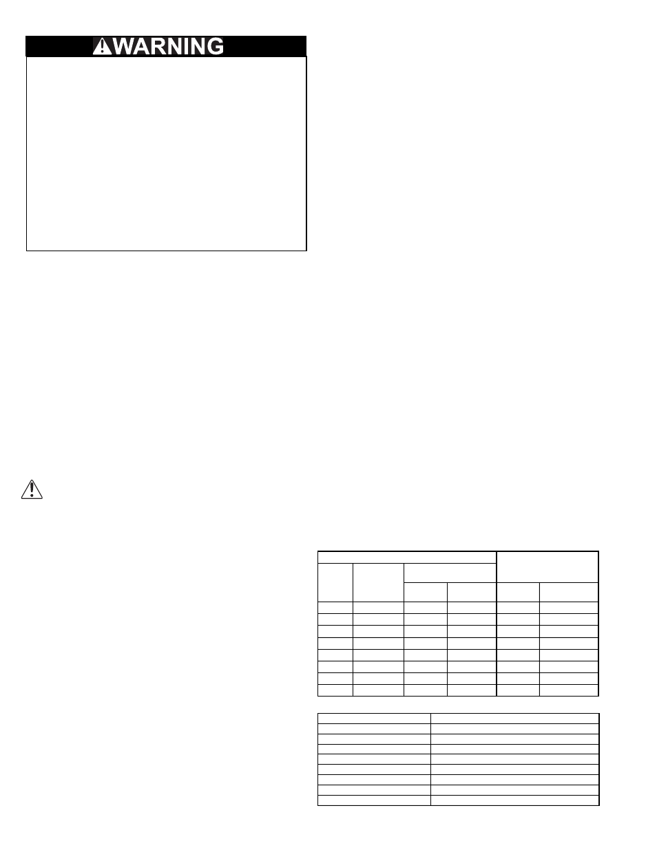
1. Ensure fasteners and set screws, particularly fan
mounting and bearing fasteners are tightened
according to the recommended torque shown on the
table below.
2. Inspect for correct amperage with an ammeter and
correct voltage with a voltmeter.
3. Ensure that all accessories are installed.
4. Test the fan to be sure the rotation is the same as
indicated by the arrow marked ‘Rotation’.
NOTICE! Do not allow the fan to run in the wrong
direction. This will overheat the motor and cause
serious damage. For 3-phase motors, if the fan is
running in the wrong direction, check the control
switch. It is possible to interchange two leads at
this location so that the fan is operating in the
correct direction.
5. Inspect wheel-to-inlet clearance. Wheels may shift in
shipment. To realign wheel-to-inlet, shift upper bearing
so there is an equal radial clearance between the wheel
and inlet. Refer to wheel to inlet clearance on page 6.
Recommended Torque for Setscrews/Bolts on metal(IN-LB)
Recommended Torque for Setscrews/Bolts on FRP (FT-LB)
Setscrews
Hold Down Bolts
Size
Key Hex
Across
Flats
Recommended
Torque
Min.
Max.
Size
Wrench
Torque
No.10
3/32”
28
33
3/8”-16
240
1/4”
1/8”
66
80
1/2”-13
600
5/16”
5/32”
126
156
5/8”-11
1200
3/8”
3/16”
228
275
3/4”-10
2100
7/16”
7/32”
29
348
7/8”-9
2040
1/2”
1/4”
42
504
5/8”
5/16”
92
1104
3/4”
3/8”
120
1440
Size (inches)
18-8 SST Hardware Torque
No 10
7
1/4”
12
5/16”
20
3/8”
30
7/16”
41
1/2”
54
5/8”
86
3/4”
128