Operation, Wiring diagrams, Pre-start checks – COOK FCRU User Manual
Page 3: Start-up, Single speed, single phase motor, Typical damper motor schematic
3
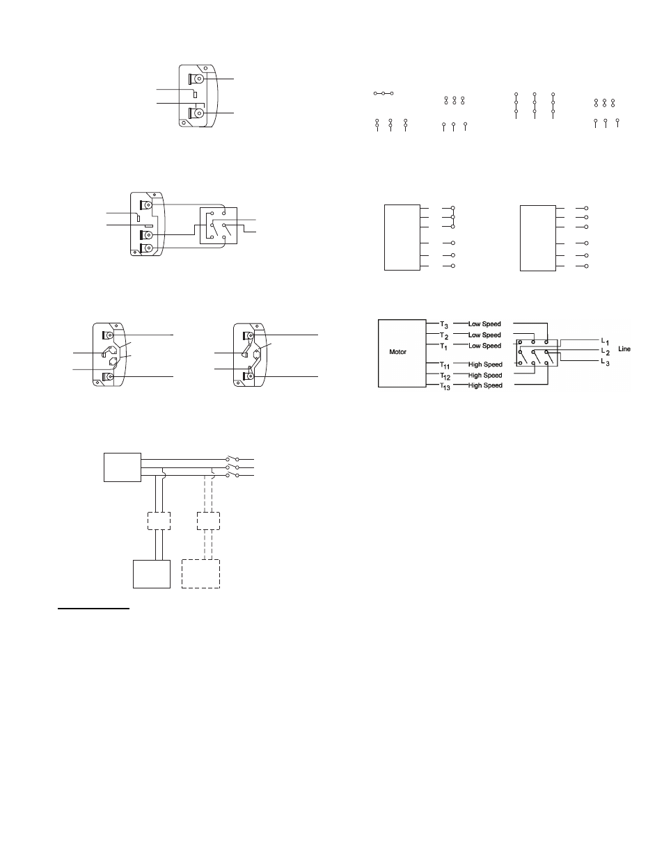
Wiring Diagrams
T-1
T-4
Ground B
L2
L1
Ground A
Line
Wiring Diagrams
When ground is required, attach to ground A or B with no. 6 thread forming
screw. To reverse, interchange T-1 and T-4.
Single Speed, Single Phase Motor
To reverse, interchange any 2 line leads.
When ground required, attach to ground A or B with No. 6 thread forming
screw. To reverse, interchange T-1 and T-4 leads.
2 Speed, 2 Winding, Single Phase Motor
2 Speed, 1 Winding, 3 Phase Motor
To reverse, interchange any 2 line leads. Motors require magnetic control.
Single Speed, Single Phase, Dual Voltage
2 Speed, 2 Winding, 3 Phase
When ground required, attach to ground A or B with No. 6 thread forming
screw. To reverse, interchange T-5 and J-10 leads.
To reverse: High Speed-interchange leads T
11
and T
12
.
Low Speed-interchange leads T
1
and T
2
. Both Speeds-interchange any 2
line leads.
Typical Damper Motor Schematic
Operation
Pre-Start Checks
1. Lock out all the primary and secondary power sources.
2. Inspect and tighten fasteners and setscrews, particularly
fan mounting and bearing fasteners Refer to Torque chart.
3. Inspect belt tension and pulley alignment. Refer to Belt
and Pulley Installation, page 4.
4. Inspect motor wiring. Refer to Wiring Installation.
5. Ensure belt touches only the pulleys.
6. Rotate the wheel to ensure it rotates freely.
7. Ensure fan and ductwork are clean and free of debris.
8. Close and secure all access doors.
9. Restore power to fan.
Start-up
Turn on the fan. In variable speed units, set the fan to its
lowest speed. Inspect for the following:
• Direction of rotation
• Excessive vibration
• Excessive vibration
• Unusual noise
• Bearing noise
• Improper belt alignment or tension (listen for squealing)
• Improper motor amperage or voltage
If a problem is discovered, immediately shut the fan
off. Lock out all electrical power and check for the cause
of the trouble. Refer to Troubleshooting on page 6.
For 3 phase, damper motor voltage should be the same between L
1
and
L
2
. For single phase application, disregard L
3
. *Damper motors may be
available in 115, 230 and 460 volt models. The damper motor nameplate
voltage should be verified prior to connection. ** A transformer may be
provided in some installations to correct the damper motor voltage to the
specified voltage.
Fan
Motor
Damper
Motor*
Second
Damper
Motor
Transformer**
Transformer**
L3
L2
L1
Ground A
Ground B
T-1
T-4
Low Speed
High Speed
L 1
L 2
Line
Ground B
J-10
T-5
Ground A
Link A
Link B
Low Voltage
Line
L 2
L 1
Ground A
Link A & B
L1
L 2
Line
Ground B
T-5
J-10
Motor
1
2
3
4
5
6
Together
High Speed
Line
L1
L2
L3
1
2
3
4
5
6
Open
Low Speed
Line
L1
L2
L3
Motor
4 5 6
1
7
2
8
3
9
L1 L2 L3
4 5 6
7 8 9
1 2
3
L1 L2 L3
Low Voltage
208/230 Volts
High Voltage
460 Volts
3 Phase, 9 Lead Motor
Y-Connection
7
1
6
7 8 9
4 5 6
1 2
3
Low Voltage
208/230 Volts
High Voltage
460 Volts
8
2
4
9
3
5
L1
L3
L2
L1
L3
L2
3 Phase, 9 Lead Motor
Delta-Connection