Replacement, Troubleshooting, Pulley and belt replacement – COOK CCP User Manual
Page 6: Bearing replacement
6
torque chart.
o. Turn the shaft by hand. Resistance should be the
same as it was before hold-down bolts were fully tight-
ened.
p. Tighten bearing setscrews to specified torque.
q. Re-install the pulley and adjust the belt tension.
Refer to Belts and Pulley Installation.
r. Test run and retighten all setscrews and bolts and trim
balance as necessary (.0785 in/sec max.).
After 24 hours of operation, retighten the setscrews to the
appropriate torque. This assures full locking of the inner
race to the shaft. Make sure the socket key or driver is in
good condition with no rounded corners. The key should be
fully engaged in the setscrew and held squarely to prevent
rounding out of the setscrew socket when applying
maximum torque.
Troubleshooting
Problem and Potential Cause
Low Capacity or Pressure
•Incorrect direction of rotation. Make sure the fan rotates in same di-
rection as the arrows on the motor or belt drive assembly.
•Poor fan inlet conditions. There should be a straight clear duct at the
inlet.
•Improper wheel alignment.
Excessive Vibration and Noise
•Damaged or unbalanced wheel.
•Belts too loose; worn or oily belts.
•Speed too high.
•Incorrect direction of rotation. Make sure the fan rotates in same di-
rection as the arrows on the motor or belt drive assembly.
•Bearings need lubrication or replacement.
•Fan surge or incorrect inlet or outlet condition.
Overheated Motor
•Motor improperly wired.
•Incorrect direction of rotation. Make sure the fan rotates in same di-
rection as the arrows on the motor or belt drive assembly.
•Cooling air diverted or blocked.
•Improper inlet clearance.
•Incorrect fan RPMs.
•Incorrect voltage.
Overheated Bearings
•Improper bearing lubrication
•Excessive belt tension.
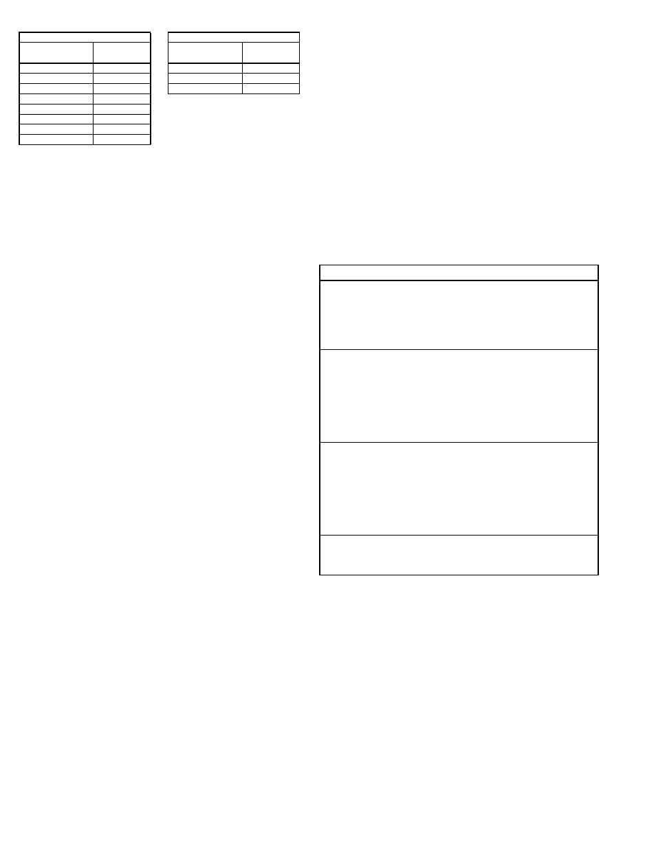
RPM Derating Factor
For elevated airstream temperatures, the maximum fan speed limits must be derated
by the factors above.
Pulley and Belt Replacement
a. Remove pulleys from their respective shafts.
b. Clean the motor and fan shafts.
c. Clean bores of pulleys and coat the bores with heavy
oil.
d. Remove grease, rust, or burrs from the pulleys
e. Remove burrs from shaft by sanding.
f. Place fan pulley on fan shaft and motor pulley on its
shaft. Damage to the pulleys can occur when exces-
sive force is used in placing the pulleys on their
respective shafts.
g. Tighten in place.
h. Install belts on pulleys and align as described in the
Belt and Pulley Installation section.
Bearing Replacement
The fan bearings are pillow block ball bearings.
An emery cloth or file may be needed to remove imper-
fections in the shaft left by the setscrews.
a. Mark the location on the shaft of both bearing races,
setscrews, and the wheel and pulley. Mark the location
and orientation of the inlet cone. Note the clearance
between the wheel and inlet cone.
b. Remove the pulley.
c. Remove the inlet cone.
d. Remove the wheel from the shaft. A 2-jaw puller may
be required.
e. Remove bearing hold-down bolts. Remove shaft and
bearings as one unit.
f. Remove the anti-corrosion coating from the shaft with
a suitable degreaser.
g. Remove the bearing from the shaft using a bearing
puller. If a bearing puller is not available, tap on the
bearing with a wood block and hammer to remove it.
h. Smooth and clean the shaft and bearing bore thor-
oughly.
i. Place the bearings into position making sure they are
not on a worn section of the shaft. Tapping the inner
ring face with a soft driver may be required.
Do not hammer on the housing.
j. The outer ring of the bearing is spherical and swivels in
the housing to compensate for misalignment. Secure
hold-down bolts, but do not fully tighten.
k. Align the setscrews on the bearings and tighten one
setscrew on each bearing.
l. Rotate the shaft to allow the bearing outer rings to find
their center of free movement.
m. Install the wheel on the shaft. Install the inlet cone in
its original location. And adjust bearing position and
inlet cone to center the wheel in the inlet cone.
n. Tighten hold-down bolts to proper torque. Refer to
Steel
Aluminum
Operating
Temperature (°F)
Speed Limit
Factor
Operating
Temperature (°F)
Speed Limit
Factor
70
1.00
70
1.00
200
0.98
200
0.93
300
0.96
300
0.79
400
0.94
500
0.91
600
0.87
700
0.81
800
0.75