Wiring diagrams, Pulley, Single speed, single phase motor – COOK CCP User Manual
Page 3: Typical damper motor schematic
3
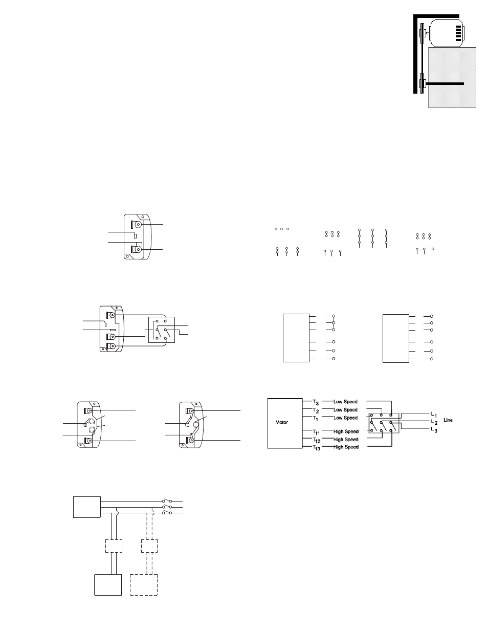
Wiring Diagrams
Fan
Motor
Damper
Motor*
Second
Damper
Motor
Transformer**
Transformer**
L3
L2
L1
Ground A
Ground B
T-1
T-4
Low Speed
High Speed
L1
L2
Line
Ground B
J-10
T-5
Ground A
Link A
Link B
Low Voltage
Line
L 2
L 1
Ground A
Link A & B
L1
L 2
Line
Ground B
T-5
J-10
4 5 6
1
7
2
8
3
9
L1 L2 L3
4 5 6
7 8 9
1 2
3
L1 L2 L3
Low Voltage
208/230 Volts
High Voltage
460 Volts
3 Phase, 9 Lead Motor
Y-Connection
Motor
1
2
3
4
5
6
Together
High Speed
Line
L1
L2
L3
1
2
3
4
5
6
Open
Low Speed
Line
L1
L2
L3
Motor
Wiring Diagrams
When ground is required, attach to ground A or B with no. 6 thread form-
ing screw. To reverse, interchange T-1 and T-4.
Single Speed, Single Phase Motor
To reverse, interchange any 2 line leads.
When ground required, attach to ground A or B with No. 6 thread forming
screw. To reverse, interchange T-1 and T-4 leads.
2 Speed, 2 Winding, Single Phase Motor
2 Speed, 1 Winding, 3 Phase Motor
To reverse, interchange any 2 line leads. Motors require magnetic control.
Single Speed, Single Phase, Dual Voltage
2 Speed, 2 Winding, 3 Phase
When ground required, attach to ground A or B with No. 6 thread forming
screw. To reverse, interchange T-5 and J-10 leads.
To reverse: High Speed-interchange leads T
11
and T
12
.
Low Speed-interchange leads T
1
and T
2
. Both Speeds-interchange any 2
line leads.
Typical Damper Motor Schematic
For 3 phase, damper motor voltage should be the same between L
1
and
L
2
. For single phase application, disregard L
3
. *Damper motors may be
available in 115, 230 and 460 volt models. The damper motor nameplate
voltage should be verified prior to connection. **A transformer may be pro-
vided in some installations to correct the damper motor voltage to the
specified voltage.
T-1
T-4
Ground B
L2
L1
Ground A
Line
7
1
6
7 8 9
4 5 6
1 2
3
Low Voltage
208/230 Volts
High Voltage
460 Volts
8
2
4
9
3
5
L1
L3
L2
L1
L3
L2
3 Phase, 9 Lead Motor
Delta-Connection
Pulley Alignment
Pulley alignment is adjusted by loosen-
ing the motor pulley setscrew and by
moving the motor pulley on the motor
shaft.
Figure 2 indicates where to measure the
allowable gap for the drive alignment tol-
erance. All contact points (indicated by
WXYZ) are to have a gap less than the
tolerance shown in the table. When the
pulleys are not the same width, the
allowable gap must be adjusted by half of the difference in
width (As shown in A & B of Figure 2). Figure 3 illustrates
using a carpenter’s square to adjust the position of the
motor pulley until the belt is parallel to the longer leg of the
square.
consulted for recommended line impedence and usage
of line reactors or filters, if the lead length between the
VFD and the motor exceeds 10 feet (3m).
Fan -
It is the responsibility of the installing body to perform
coast-down tests and identify any resonant frequencies
after the equipment is fully installed. These resonant fre-
quencies are to be removed from the operating range of
the fan by using the “skip frequency” function in the VFD
programming. Failure to remove resonant frequencies
from the operating range will decrease the operating life
of the fan and void the warranty.
Belt and Pulley Installation continued
c. Lock the motor plate adjustment bolts in place.
d. Ensure pulleys are properly aligned. Refer to Figure
2.
Figure 3