Use of variable frequency drives – COOK CCP User Manual
Page 2
2
115 and 230 Single Phase Motors
Fan wheel rotation is set correctly at the factory. Chang-
ing the rotation of this type of motor should only be
attempted by a qualified electrician.
208, 230, and 460, 3 Phase Motors
These motors are electrically reversible by switching two
of the supply leads. For this reason, the rotation of the fan
cannot be restricted to one direction at the factory. See
Wiring Diagrams on page 3 for specific information on
reversing wheel direction.
NOTICE! Do not allow the fan to run in the wrong
direction. This will overheat the motor and cause seri-
ous damage. For 3-phase motors, if the fan is running
in the wrong direction, check the control switch. It is
possible to interchange two leads at this location so
that the fan is operating in the correct direction.
Belt and Pulley Installatio
n
Belt tension is determined by the sound the belts make
when the fan is first started. Belts will produce a loud
squeal which dissipates after the fan is operating at full
capacity. If the belt tension is too tight or too loose, lost effi-
ciency and possible damage can occur.
Do not change the pulley pitch diameter to change ten-
sion. This will result in a different fan speed than desired.
a. Loosen motor plate adjustment bolts and move motor
plate in order that the belts can easily slip into the
grooves on the pulleys. Never pry, roll, or force the
belts over the rim of the pulley.
b. Slide the motor plate back until proper tension is
reached. For proper tension a deflection of approxi-
mately 1/4” per foot of center distance should be
obtained by firmly pressing the belt. Refer to Figure 1.
Use of Variable Frequency Drives
Motors -
Motors that are to be operated using a Variable Fre-
quency Drive (VFD) must be VFD compatible. At a mini-
mum, this must be a Premium Efficiency motor with Class F
insulation. Motors that are not supplied by Loren Cook
Company should have the recommendation of the motor
manufacturer for use with a VFD.
Grounding -
The fan frame, motor and VFD must be connected to a
common earth ground to prevent transient voltages from
damaging rotating elements.
Wiring -
Line reactors may be required to reduce over-voltage
spikes in the motors. The motor manufacturer should be
1 foot
1/4 inch
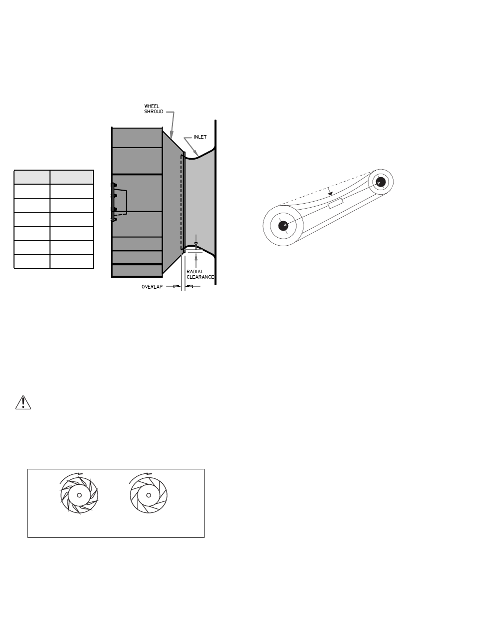
Figure 1
Wheel-to-Inlet Clearance
The correct wheel-to-inlet clearance is critical to proper
fan performance. This clearance should be verified before
initial start-up since rough handling during shipment could
cause a shift in fan components. Refer to wheel/inlet draw-
ing for correct overlap.
Adjust the overlap by loosening the wheel hub and mov-
ing the wheel along the shaft to obtain the correct value.
A uniform radial gap
(space between the edge of
the cone and the edge of
the inlet) is obtained by
loosening the inlet cone
bolts and repositioning the
inlet cone.
Wiring Installation
All wiring should be in
accordance with local ordinances and the National Electri-
cal Code, NFPA 70. Ensure the power supply (voltage, fre-
quency, and current carrying capacity of wires) is in
accordance with the motor nameplate.
Leave enough slack in the wiring to allow for motor
movement when adjusting belt tension. Some fractional
motors have to be removed in order to make the connec-
tion with the terminal box at the end of the motor. To
remove motor, remove bolts securing motor base to power
assembly. Do not remove motor mounting bolts.
Follow the wiring diagram in the disconnect
switch and the wiring diagram provided with the
motor. Correctly label the circuit on the main
power box and always identify a closed switch
to promote safety (i.e., red tape over a closed
switch).
Wheel Rotation
Test the fan to ensure the rotation of the wheel is the
same as indicated by the arrow marked Rotation.
Size
Overlap
100 - 165
3/16”
180 - 245
1/4”
270 - 300
5/16”
330 - 365
3/8”
402
7/16”
445 1/2”
Airfoil
Backward
Inclined
Proper Wheel Rotation