Vertical contact toaster, Vertical contact toaster vct-20, Maintenance (continued) – A.J. Antunes & Co VCT-20 9200552 User Manual
Page 16
16
VERTICAL CONTACT TOASTER
P/N 1010719 Rev. E 02/13
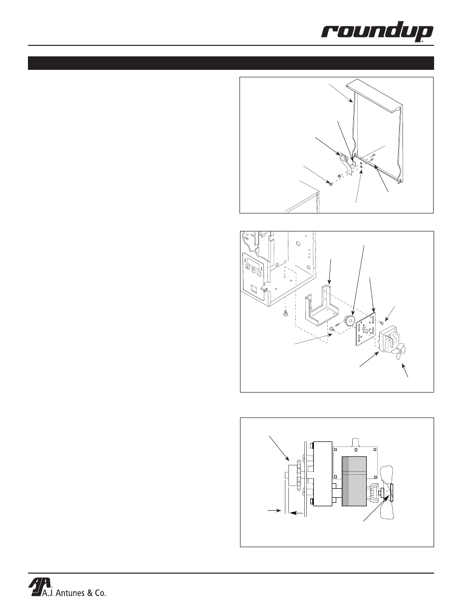
Rear Conveyor Cover Assy.
Weld Screws
Tape
Acorn Nuts
Spacers
Tensioner Assy.
Figure 15. Replacing Roller Tensioner Assy.
5. Place one drop of treadlocker into each threaded
hole in the gear reducer casting. Attach the drive
motor bracket to the gear reducer using the origi-
nal four 10-32 x 3/8" screws (310P154) removed
in step 3.
6. Attach the motor sprocket to the gear reducer as
shown in Figure 16.
NOTE: Be sure sprocket setscrew is positioned on
the flat of the gear reducer shaft. Maintain the
3/16" dimension as shown in Figure 17. Apply
threadlocker to threads of setscrew and tighten
securely.
7. Using the four new 8-32 x 5/16" stainless steel
SEMS truss head screws (P/N 308P151), attach
the drive motor bracket to the mounting bracket.
DO NOT tighten screws at this time.
8. Place the drive chain on the sprocket and push
down on motor. Allow 1/4" (0.6 mm) play at mid-
dle of drive chain, then tighten mounting screws
while holding motor. Check drive chain play after
tightening screws.
9. Re-connect motor wires, one at a time.
10. Re-install control cover.
Apply only 1 drop of threadlocker to front of fan assy. after
assembly. Outer edge of fan blade hub to be flush with end of
motor shaft.
3/16"
(4.75 mm)
Apply threadlocker on setscrew of sprocket and all other
mounting screws.
Figure 17. Replacing Drive Motor and Fan Blade
MAINTENANCE (continued)
Figure 16. Replacing Drive Motor and Fan Blade
POW
ER
TEMP
DOWN
TEMP
UP
TEMP
SCALE
˚C
˚F
Fan Blade
Motor Sprocket
Drive Motor/Gear Reducer - Place 1 drop of
threadlocker into each threaded mounting
hole of reducer before installing.
Drive Motor
Bracket
Mounting
Bracket Screw
(308P151)
Motor Mounting
Screw (310P154)
Mounting
Bracket
VERTICAL CONTACT TOASTER VCT-20
14
P/N 1010719 Rev. C 12/99
A.J. Antunes & Co.
Rear Conveyor Cover Assy.
Weld Screws
Acorn Nuts
Spacers
Tensioner Assy.
Teflon Tape
Figure 18. Replacing Roller Tensioner Assy.
5. Place one drop of Loctite (Blue) into each thread-
ed hole in the gear reducer casting. Attach the
drive motor bracket to the gear reducer using the
original four 10-32 x 3/8" screws (310P154)
removed in step 3.
6. Attach the motor sprocket to the gear reducer as
shown in Figure 19.
NOTE: Be sure sprocket setscrew is positioned on the
flat of the gear reducer shaft. Maintain the 3/16"
dimension as shown in Figure 20. Apply Loctite (Blue)
to threads of setscrew and tighten securely.
7. Using the four new 8-32 x 5/16" stainless steel
SEMS truss head screws (P/N 308P151), attach
the drive motor bracket to the mounting bracket.
DO NOT tighten screws at this time.
8. Place the drive chain on the sprocket and push
down on motor. Allow 1/4" (0.6 mm) play at mid-
dle of drive chain, then tighten mounting screws
while holding motor. Check drive chain play after
tightening screws.
9. Re-connect motor wires, one at a time.
10. Re-install control cover.
Apply only 1 drop of Loctite (RED) to front of fan assy. after
assembly. Outer edge of fan blade hub to be flush with end of
motor shaft.
3/16"
(4.75 mm)
Apply Loctite (BLUE) on setscrew of sprocket and all other
mounting screws.
Figure 20. Replacing Drive Motor and Fan Blade
MAINTENANCE (continued)
Figure 19. Replacing Drive Motor and Fan Blade
POW
ER
TEMP
DOW
N
TEMP
UP
TEMP
SCALE
˚C
˚F
Fan Blade
Motor Sprocket
Drive Motor/Gear Reducer - Place 1 drop of
Loctite (Blue) into each threaded mounting
hole of reducer before installing.
Drive Motor
Bracket
Mounting
Bracket Screw
(308P151)
Motor Mounting
Screw (310P154)
Mounting
Bracket