Vertical contact toaster – A.J. Antunes & Co VCT-20 9200552 User Manual
Page 15
15
VERTICAL CONTACT TOASTER
P/N 1010719 Rev. E 02/13
Stainless Steel Conveyor Belts–Removing,
Servicing & Replacing
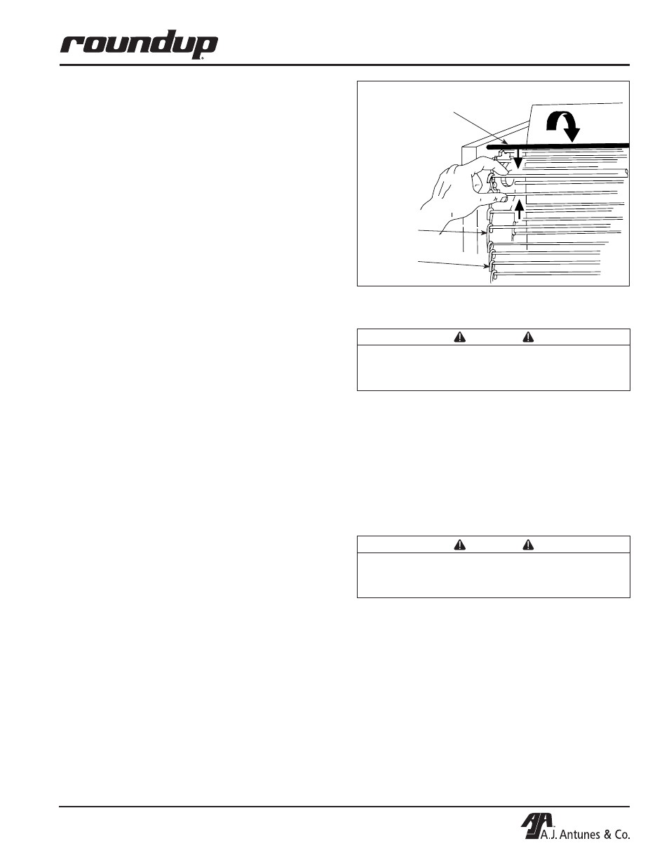
REMOVING THE CONVEYOR BELT
1. Perform steps 1 - 4 under Replacing Belt Wraps
on the previous page.
NOTE: When replacing conveyor belt, it is recom-
mended that the release sheet and conveyor belt
wrap cleaning procedures be performed.
2. Disconnect the conveyor belt by squeezing any
two links together and unhooking both ends of
one link (Figure 14). Remove conveyor belt.
NOTE: With conveyor belt removed, the tensioner
assemblies 4, page 30) and slide rails (40, page 30)
can be replaced.
SERVICING CONVEYOR BELTS
After a period of time, the conveyor rods will wear and
the conveyor belt will stretch. This will eventually
cause the conveyor to jam as it rotates on the sprock-
ets. This is easily remedied by removing one or more
conveyor links from each side of the belt.
There are four 1/2" long links
on each side of the con-
veyor belt. The rest of the links are 3/4" long.
1. Remove conveyor belt as described previously on
this page.
2. To shorten a stretched conveyor belt, remove one
1/2" link from the belt.
3. Reassemble the belt to the sprockets as
described below.
NOTE: If the belt is too short to be reassembled,
remove an additional 1/2" link and install a 3/4"
link. This will shorten the belt 1/4" overall.
REPLACING CONVEYOR BELTS
1. Remove old conveyor belt as described previous-
ly on this page.
2. Place replacement conveyor belt on top sprock-
ets. Check for correct positioning (Figure 14).
NOTE: Install conveyor belt so that the ends of the
hooks are facing down.
3. Wrap conveyor belt around lower sprockets and
connect by hooking both ends of the belt back
together.
4. Perform steps 5 - 11 under Replacing Belt Wraps
(previous page).
Replacing Roller Tensioners
1. Remove acorn nuts (Figure 15).
2. Remove old roller tensioner assy.
3. Replace tensioner assy. and reassemble.
4. Make sure the spacers are placed inside the ten-
sioner arm. The spacers are smaller than the
holes to allow the tensioner to pivot freely.
Replacing Conveyor Motor and Fan Blade
NOTE: A small amount of threadlocker is required
for proper gear motor installation.
1. Remove control cover (8, Page 25)
2. Disconnect the motor wires and remove the drive
motor and drive motor bracket (Figure 19).
Discard the 8-32 x 5/16" mounting bracket
screws.
3. Remove the motor sprocket using a hex wrench.
4. Remove the drive motor bracket from the gear
motor. Save the four 10-32 x 3/8" pan head
screws (P/N 310P154).
Figure 14. Removing Conveyor Belt
Rotation
Upper Support Rod
Large Link
P/N 0800121
Small Link
P/N 0800204
WARNING
Turn the unit off, disconnect the power source
and allow the unit to cool down before performing
any service or maintenance on the unit.
WARNING
Turn the unit off, disconnect the power source
and allow the unit to cool down before performing
any service or maintenance on the unit.