Allied Telesis AT-3714FXL User Manual
Page 24
Installing the Switch
2-6
4. Mount the unit in the rack.
5. Apply power to the unit as follows:
Caution
Power cord is used as a disconnection device. To de-energise
equipment disconnect the power cord.
"
10
Attach the power cord to the unit and plug it in the wall outlet.
Verify that the Power LED lights green. As power is applied to the
switch, the switch runs its own internal testing. See Table 2-1,
LEDs.
If the Power LED does not light green, see Chapter 3,
Troubleshooting for further information.
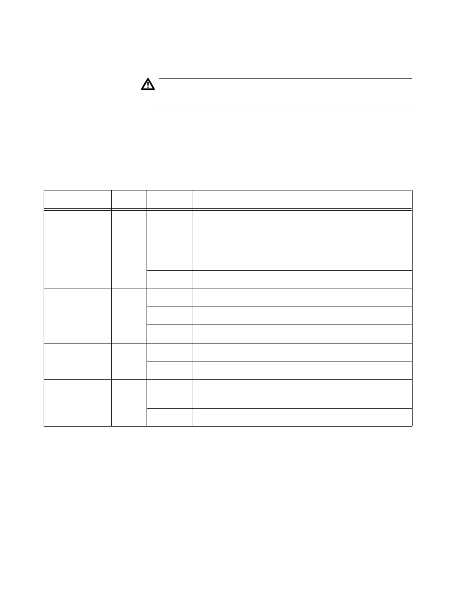
Table 2-1 LEDs
LED
Color
State
Description
Power (system)
Green
On
The switch is receiving power, voltage is within the
acceptable range, and the power supply is working.
Note: if only the management software is
malfunctioning, the switch continues to forward
packets.
Off
No power.
Fault (system)
Red
On
The switch or management software is malfunctioning.
Off
Normal operation.
Flashing
Running diagnostics.
Link
Green
On
There is a physical link with a device.
Off
No link.
Activity
Green
Flashing
or On
The Ethernet port is receiving/transmitting packets.
Off
No transmits or receives occurring on this port.