Pinout assignments – Allied Telesis AT-FS217 User Manual
Page 30
Technical Specifications
20
Table 8 Fiber Optic Loss Specification (Benchmarks)
Pinout Assignments
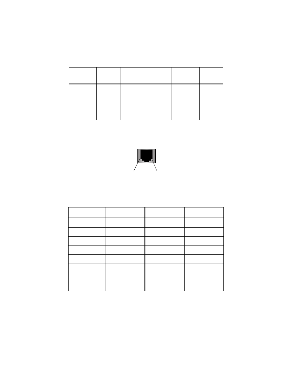
Figure 7 shows the pin assignments of the switch’s 10/100Base-TX RJ-45 port.
Figure 7 RJ-45 Pin Assignments
Table 9 lists the RJ-45 connector pins and their signals for 10/100Base-TX.
Table 9 RJ-45 Pin Signals
Fiber Type
Fiber Optic
Diameter
Optical
Frequency
Typical
Loss Factor
Worst Case
Loss Factor
Bandwidth
Multimode
Fiber
50/125
1310 nm
1.00 db/km
1.50 db/km
400
62.5/125
1310 nm
1.00 db/km
1.5 db/km
500
Single-mode
9/125 nm
1310 nm
0.40 db/km
1.00 db/km
N/A
9/125 nm
1550 nm
0.30 db/km
0.75 db/km
N/A
MDI-X (Default)
Signal
MDI
Signal
1
RX+
1
TX+
2
RX-
2
TX-
3
TX+
3
RX+
4
-
4
-
5
-
5
-
6
TX-
6
RX-
7
-
7
-
8
-
8
-
Pin 1
Pin 8
This manual is related to the following products: