Allied Telesis AT-FS217 User Manual
Page 12
Overview
2
These switches are easy to install and do not require software configuration or
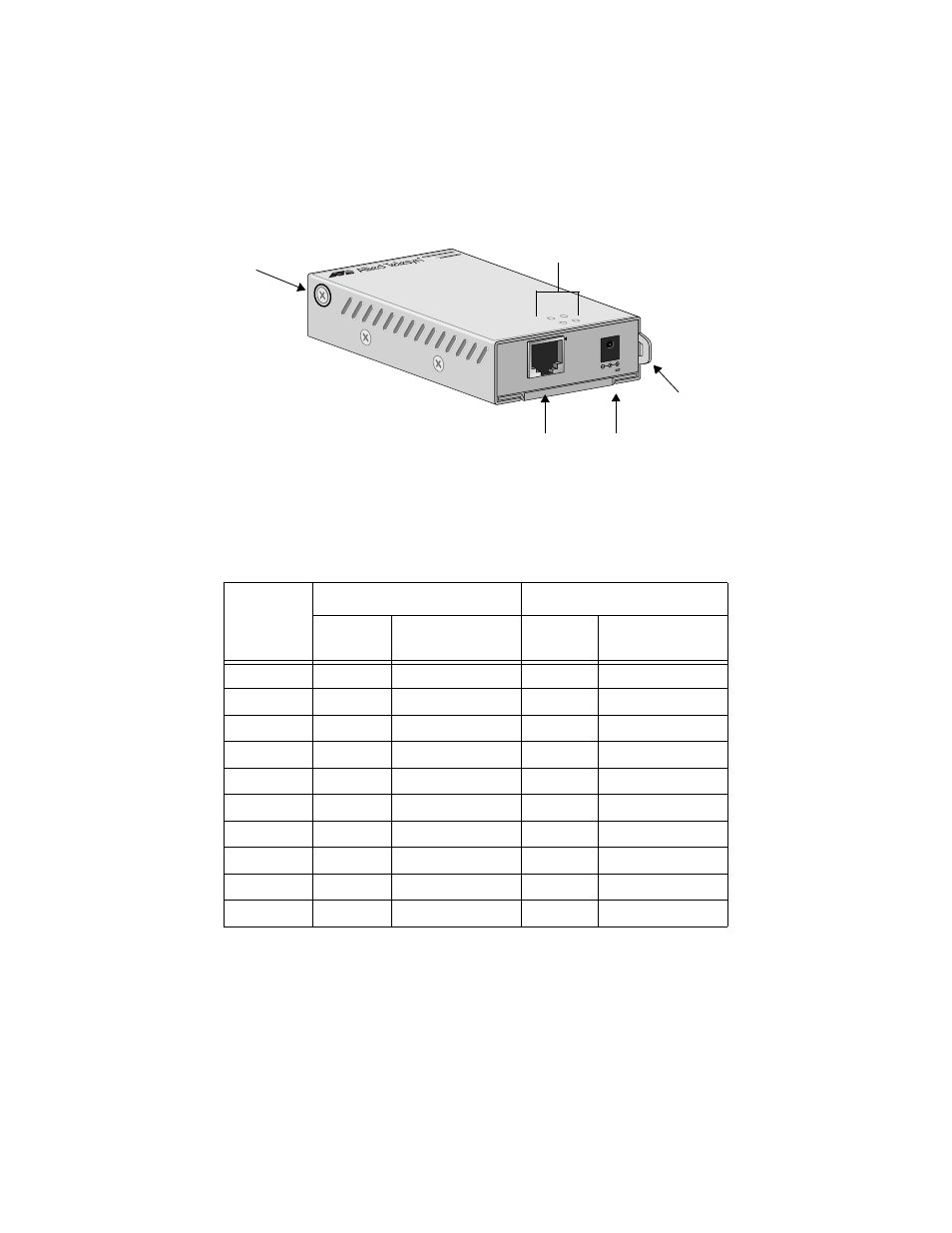
management. Figure 1 illustrates an AT-FS21x Series Switch.
Figure 1 AT-FS21x Series Switch (Model AT-FS214)
Table 1 lists the operating distances for the AT-FS21x and AT-FS212/x Series
Switches.
Table 1 Maximum Operating Distance
Model
10/100Base-TX
1
1.
Maximum distance can only be obtained when the UTP/STP cabling is installed and verified to the TIA/EIA 568A
Commercial Building Telecommunications Cabling Standard.
100Base-FX
2
2.
Maximum distance for 100 Mbps Optical Datalinks are dependent on the following factors: type of optical fiber,
duplex mode of both end-nodes, and maximum optical loss budget for each of the optical fiber at the operating
optical wavelength.
Connector
Maximum
Operating Distance
Connector
Maximum
Operating Distance
AT-FS211
RJ-45
100 m (328 ft)
ST
2 km (1.2 mi)
AT-FS212
RJ-45
100 m (328 ft)
SC
2 km (1.2 mi)
AT-FS212/1
RJ-45
100 m (328 ft)
SC
15 km (9.3 mi)
AT-FS212/2
RJ-45
100 m (328 ft)
SC
40 km (24.8 mi)
AT-FS212/3
RJ-45
100 m (328 ft)
SC
70 km (43.4 mi)
AT-FS212/4
RJ-45
100 m (328 ft)
SC
100 km (62 mi)
AT-FS214
RJ-45
100 m (328 ft)
MT-RJ
2 km (1.2 mi)
AT-FS215
RJ-45
100 m (328 ft)
VF-45
2 km (1.2 mi)
AT-FS216
RJ-45
100 m (328 ft)
LC
2 km (1.2 mi)
AT-FS217
RJ-45
100 m (328 ft)
FJ
2 km (1.2 mi)
FX
TX
PWR
Fast Ether
net Switch
AT-FS
214
10Base
-T/
100Base
-TX
3.3VDC
Cable Hook
Mounting
Bracket Screws
LEDs
DC Connector
10/100Base-TX Port