Warranty registration – Allied Telesis AT-MC16 User Manual
Page 27
AT-MC1x Series Installation Guide
17
7.
Connect the twisted pair cable to the 10Base-T port.
8.
Set the MDI/MDI-X switch as follows:
—
If you are connecting a workstation to the twisted pair port, set the
MDI/MDI-X switch to the MDI-X position. (MDI-X is the default
position.)
—
If you are connecting a hub or switch to the twisted port pair, set the
MDI/MDI-X switch to the MDI position.
9.
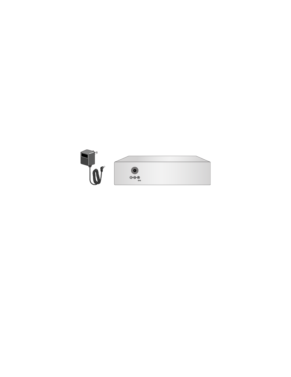
Plug the AC/DC power adapter into an appropriate AC power outlet and
insert the power plug into the DC receptacle located on the back of the
unit. This step does not apply if you installed the unit in an
AT-MCR12 chassis.
Figure 7 12 V DC Connector on the Back of the Media Converter
10. Verify that the Power LED is green. If the LED is OFF, refer to
“Troubleshooting” on page 19 for instructions.
11. Power ON the end-nodes.
12. Verify that the LNK LED for both the fiber optic port and the twisted pair
port is green. The AT-MC15 has one LNK LED for the twisted pair port. If
the LED is OFF, refer to “Troubleshooting” on page 19 for instructions.
The media converter is now ready for use.
Warranty Registration
When you finish installing the product, register your product by completing the
enclosed warranty card and sending it in. You can also fill out the registration
online at www.alliedtelesyn.com/support/warrantyf.asp.
12 V D C