Remove additional hardware, such as rackmountin, Remove the top cover from the unit, as follows, A. remove the screw from the back of the unit that – Allied Telesis AT-8203 User Manual
Page 12: B. lift the cover and slide it off (figure4), Using a #1 phillips screwdriver, remove the scr
Installing the Uplink Card
6
4.
Remove additional hardware, such as rackmounting brackets.
Note
If the switch is installed on the desktop, you need not remove the
rubber feet.
Warning
Use proper static-free procedures prior to opening the unit and
touching components.
5.
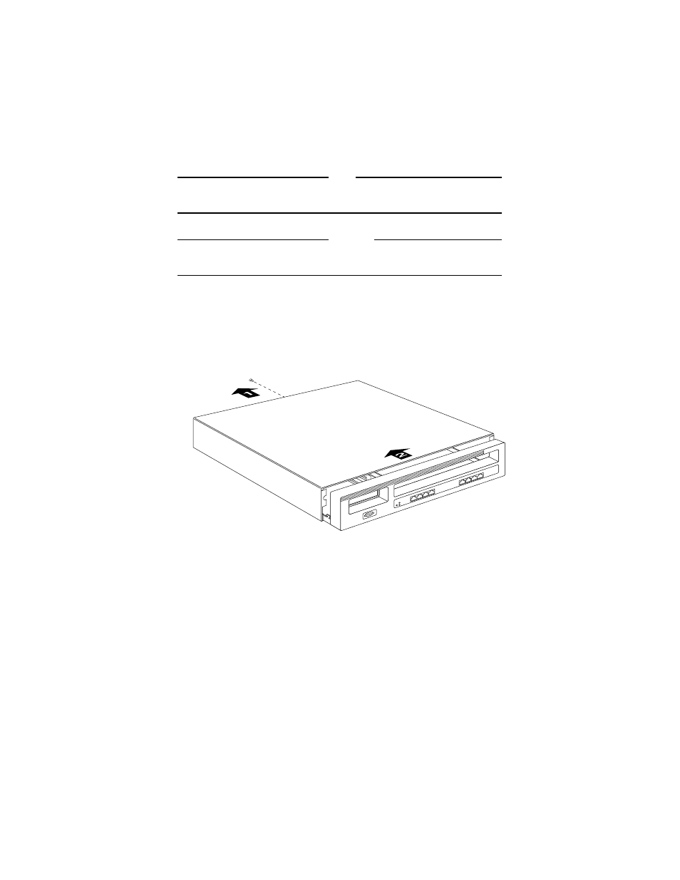
Remove the top cover from the unit, as follows:
a. Remove the screw from the back of the unit that locks the cover in
place. Retain the screw for replacing the cover later.
b. Lift the cover and slide it off (Figure 4).
Figure 4:
Chassis Top Removal
6.
Using a #1 Phillips screwdriver, remove the screw that secures the
cover plate to the uplink panel (Figure 5).
Save the screw to secure the uplink card.
This manual is related to the following products: