Figure12: connector pin numbers, Table 4: pin assignments, 10base-t pin assignments – Allied Telesis AT-MR815T User Manual
Page 35: Connectors
AT-MR415T and AT-MR815T Installation Guide
25
10Base-T Pin Assignments
An Ethernet twisted-pair link segment requires two pairs of wires. Each wire
pair is identified by solid and striped colored wires. For example, one wire in
the pair might be red and the other wire, red with white stripes.
Connectors
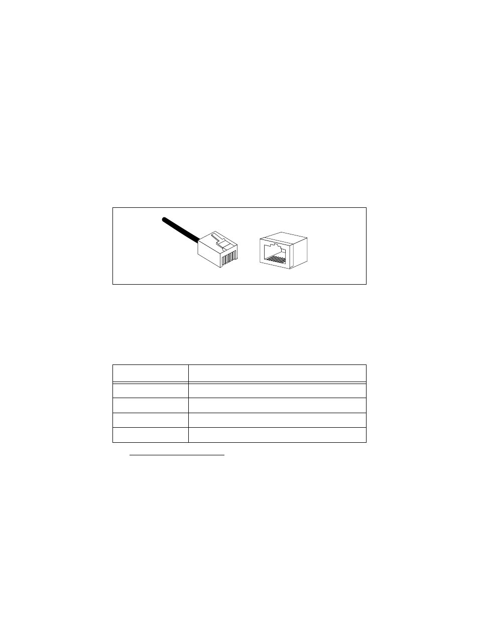
Notice how the pins are numbered in Figure 12. Be sure to hold the connectors
in the same orientation when connecting the wires to the pins.
Figure 12: Connector Pin Numbers
Each twisted-pair link segment must have a male connector attached to both
ends. According to the 10Base-T specification, pins 1 and 2 on the connector
are used for transmitting data; pins 3 and 6 are used for receiving data, as
shown in Table 4.
Table 4: Pin Assignments
*The “+” and “-” signs are used to represent the polarity of the two wires that make up each wire
pair.
Pin
Assignment *
1
TX+
2
TX-
3
RX+
6
RX-
1
8
8
1