Figure3: at-mr815t front panel, At-mr815t, Light emitting diodes (leds) – Allied Telesis AT-MR815T User Manual
Page 15
AT-MR415T and AT-MR815T Installation Guide
5
❑
MDI MDI-X Toggle Switch
— This switch allows you to set the cascade port (the port directly to
the right of this switch). This cascade port, in turn, can be used to
either connect to another repeater or as a normal 10Base-T port.
The switch positions are as follows:
MDI (left position). This port can now be used to cascade to another
repeater.
MDI-X (right position). Use this port as a normal 10Base-T port.
❑
10Base-T Connector
— There is one 10Base-T connector for each port on the unit. Connect
10Base-T cables (twisted pair cable, UTP) into the desired RJ-45
ports.
❑
DC Power Jack
— This connector is used to provide power to the unit using the AC
adapter.
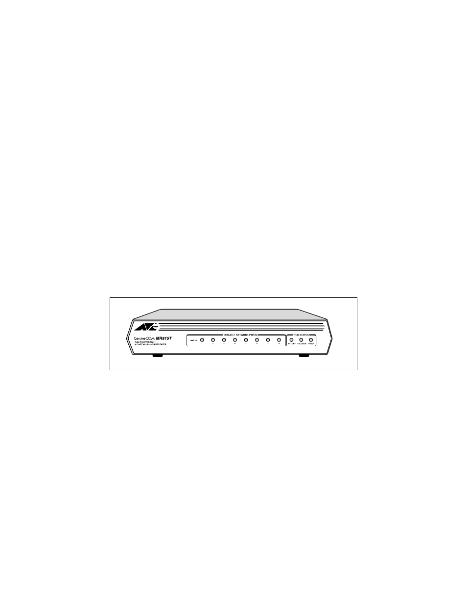
AT-MR815T
Figure 3 shows the front panel of an AT-MR815T.
Figure 3:
AT-MR815T Front Panel
Light Emitting Diodes (LEDs)
Eight LINK LEDs show the connectivity of each network port. Three
additional LEDs indicate Activity, Collision and Power for the repeater itself.
❑
LINK ON lamp (green)
— There is a green LED for each 10Base-T port. This LED is lighted
when the twisted pair cable for the corresponding 10Base-T port is
properly connected, the port has established a valid link and the
automatic port connect/disconnect function has been enabled.