Table 3: ieee 802.3 network specifications, Media, Unshielded twisted pair – Allied Telesis AT-MR815T User Manual
Page 23: Topology, Star, tree, External devices, Network adapter card, Maximum segment length, 100 meters (328 ft.), Maximum devices per segment
AT-MR415T and AT-MR815T Installation Guide
13
10Base-T Network Specifications
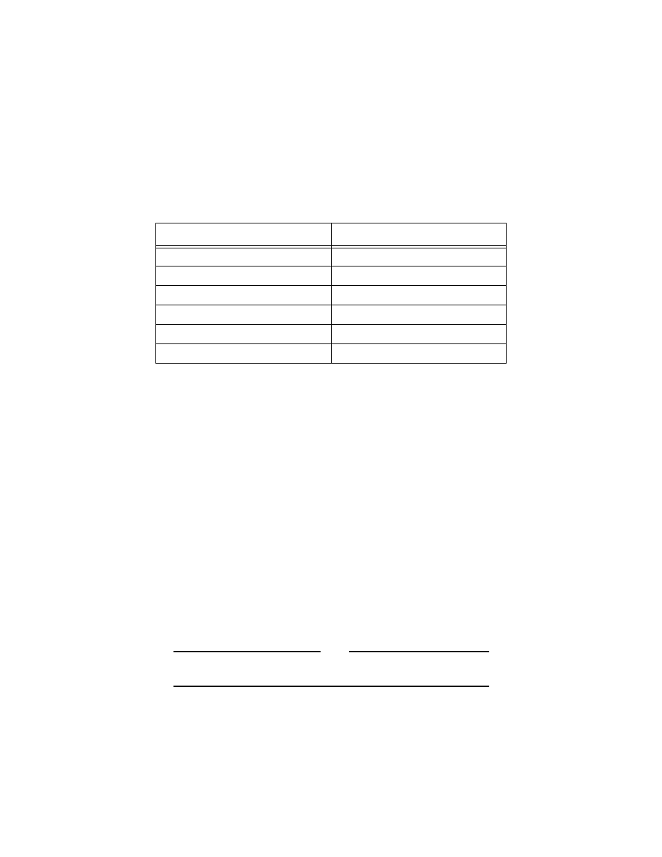
Table 3 provides an overview of the IEEE 802.3 specifications for 10Base-T
network configurations using twisted-pair wiring.
Table 3: IEEE 802.3 Network Specifications
System Check
1. Check the LINK ON LED on the front panel for the first 10Base-T port
that is connected. A steady green LED indicates continuity. A valid
network connection is made from the connected port to a host or
workstation on another port.
2. After a successful connection, disconnect the active 10Base-T connector
and connect it to the next successive port. Continue this process until all
10Base-T ports have been validated with good network connections.
3. Establish a connection from a device connected to port 1 to a device
connected to port 2.
4. Once the connection between devices attached to ports 1 and 2 has been
successfully established, remove the RJ-45 connector from port 2 and
connect it to each of the subsequent 10Base-T ports, 3 through 4 (or 2
through 8), to verify their functionality.
5. If all ports test successfully, install the rest of the 10Base-T RJ-45
connections and ensure that the LINK LED for each port is illuminated.
Remember, the 10Base-T device on the opposite end of the UTP cable must
be operational.
Note
The LINK LED validates the receive pair only. The opposite end of
the UTP segment is responsible for validating the transmit pair.
10Base-T
Media
Unshielded Twisted Pair
Topology
Star, Tree
External Devices
Network Adapter Card
Maximum Segment Length
100 meters (328 ft.)
Maximum Devices per Segment
12
Maximum Devices per Network
1024