Table 1: model configurations, At-mr415t-10, North america – Allied Telesis AT-MR815T User Manual
Page 20: 90/120 vac, At-mr815t-10, At-mr415t-20, Europe/asia, 200/240 vac, At-mr815t-20, At-mr415t-30
Installation
10
Table 1 shows the model variations and different power arrangements for
AT-MR415T/AT-MR815T Micro Repeaters:
Table 1: Model Configurations
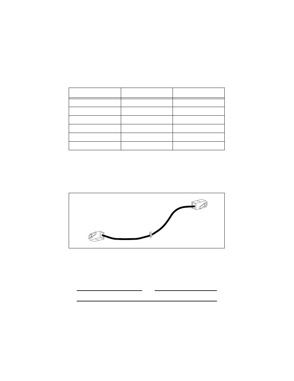
UTP (RJ-45) Connectivity
A UTP cable with RJ-45 connectors is shown in Figure 5. For a 10Base-T link
between a repeater and a Medium Attachment Unit (MAU) or Network
Interface Controller (NIC), the cable is wired straight through.
Figure 5: RJ-45 Connector
10Base-T UTP cables can be up to 100 meters (328 ft.) in length. The cable
should be 22 to 26 AWG UTP wire with 100
Ω
impedance. The AT-MR415T/
AT-MR815T Micro Repeater uses RJ-45 modular connectors for 10Base-T
connections.
Note
Do not connect standard telephone line into a signal connector.
Model
Location
Voltage
AT-MR415T-10
North America
90/120 VAC
AT-MR815T-10
North America
90/120 VAC
AT-MR415T-20
Europe/Asia
200/240 VAC
AT-MR815T-20
Europe/Asia
200/240 VAC
AT-MR415T-30
United Kingdom
200/240 VAC
AT-MR815T-30
United Kingdom
200/240 VAC