Recommended cables and cable specifications – Allied Telesis AT-MC104LH User Manual
Page 15
AT-MC104XL and AT-MC104LH Installation Guide
9
Recommended Cables and Cable Specifications
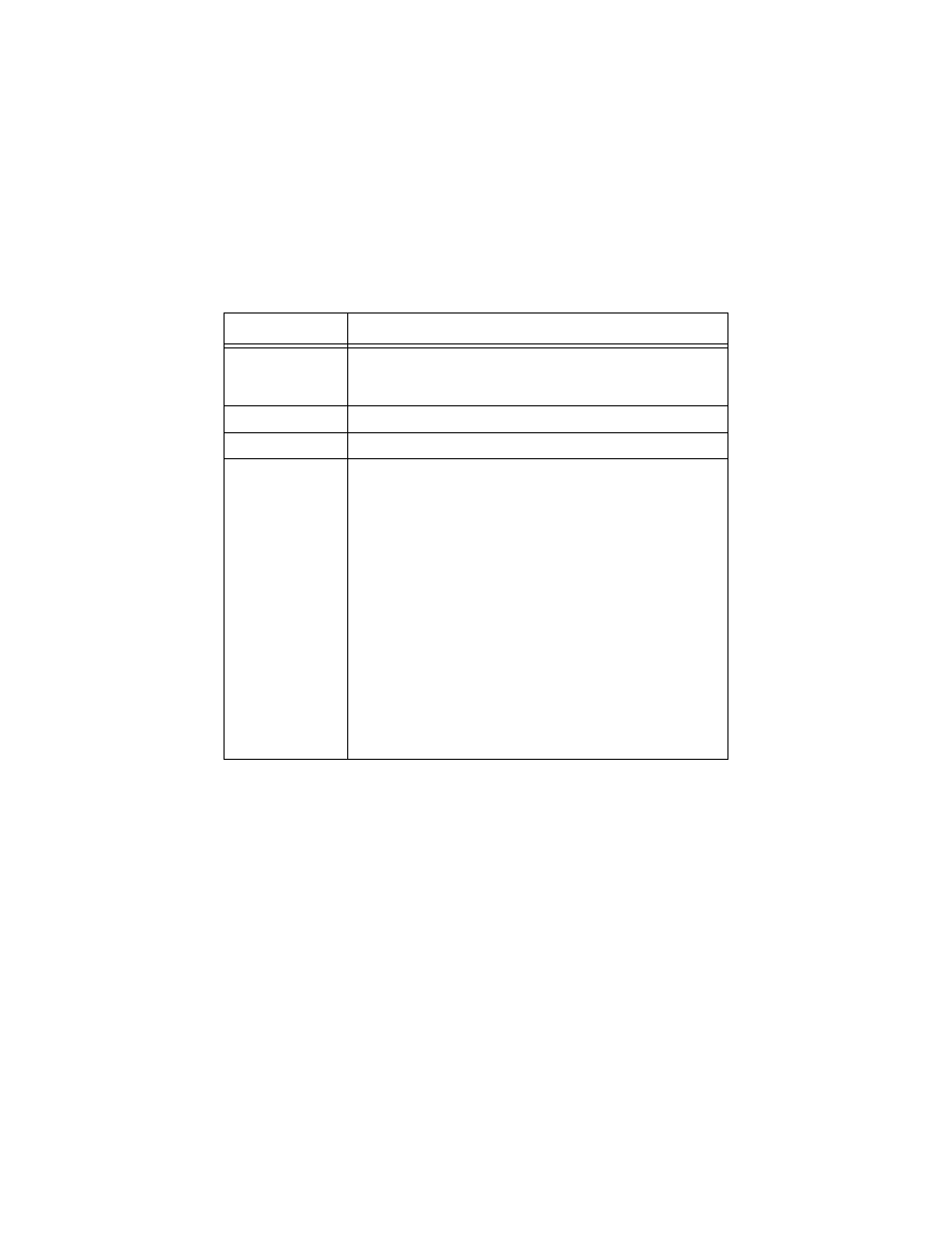
Table 3 lists the IEEE 802.3u cabling specifications. Refer to this table for
cabling recommendations.
Note 1. The Single Mode Fiber Optic Transmitter is rated as a Class 1 Laser.
Note 2. Each Media Converter used inline within a single collision domain will reduce the overall segment length by
40 m (131.24 ft) of fiber.
Note 3. Applies only to the AT-MC104XL, Single Mode Fiber Optic Transmitter/Receiver.
Note 4. Applies only to the AT-MC104LH, Single Mode Fiber Optic Transmitter/Receiver.
Table 3 IEEE 802.3u Cabling Specifications for AT-MC104XL and AT-MC104LH
100Base-FX
Media
1310 nm Multimode fiber (MMF), 50/125 micron
1310 nm Multimode fiber (MMF), 62.5/125 micron
1310 nm Single mode fiber (SMF), 9/125 micron (see Note 1)
Topology
Star, Tree
External Devices
Network Adapter Card, Repeater, Switch, Router, or Bridge
Maximum Segment
Length
100Base-FX Full-Duplex operation:
Multimode fiber (MMF), 2 km (1.2 mi)
Single mode fiber (SMF), 15 km (9.32 mi) (XL model only, see Note 3)
Single mode fiber (SMF), 40 km (24.9 mi) (LH model only, see Note 4)
100Base-FX Half-Duplex operation:
The total distance of all fiber runs cannot exceed the following limits
(see Note 2):
with one Media Converter inline:
Switch to Switch = 372 m (1221 ft)
Work Station to Switch = 372 m (1221 ft)
Switch to Class II Repeater = 185 m (607 ft)
Switch to Class I Repeater = 137 m (450 ft)
with two Media Converters inline:
Switch to Switch = 332 m (1089 ft)
Work Station to Switch = 332 m (1089 ft)
Switch to Class II Repeater =145 m (476 ft)
Switch to Class I Repeater = 97 m (318 ft)