Allied Telesis AT-8088/xx (MT and SC) User Manual
Page 61
AT-8000 Series Fast Ethernet Switches Installation Guide
61
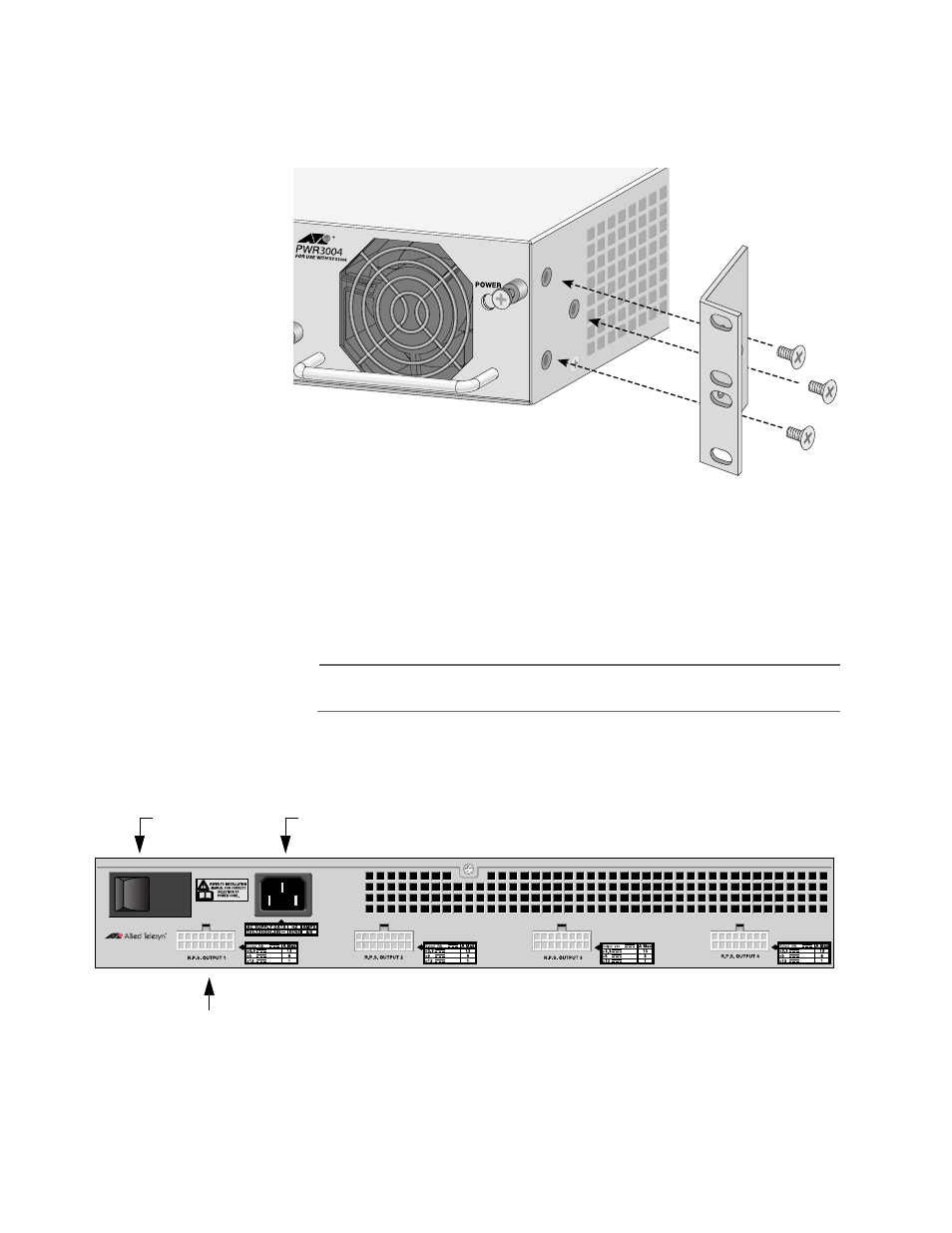
4.
Attach a rackmounting bracket to one side of the power supply
using four of the screws that came with the power supply. See
Figure 27.
Figure 27. Attaching Rackmounting Brackets
5.
Install the second rackmounting bracket on the other side of the
power supply using the four remaining screws.
6.
Mount the power supply in the 19-inch rack using standard screws
(not provided).
Note
Ensure that air flow is unrestricted around the AT-RPS3004 unit.
7.
Attach the provided DC power cord to the DC output connector on
the back panel of the AT-RPS3004 power supply. Refer to Figure 28
for the DC output connector.
Figure 28. AT-RPS3004 Unit Back Panel
ON/OFF
16-pin Molex DC Power Connector
AC Power Connector
Switch
AT-RPS3004