Collapsed backbone - hub topology – Allied Telesis AT-8088/xx (MT and SC) User Manual
Page 44
Overview
44
Collapsed
Backbone - Hub
Topology
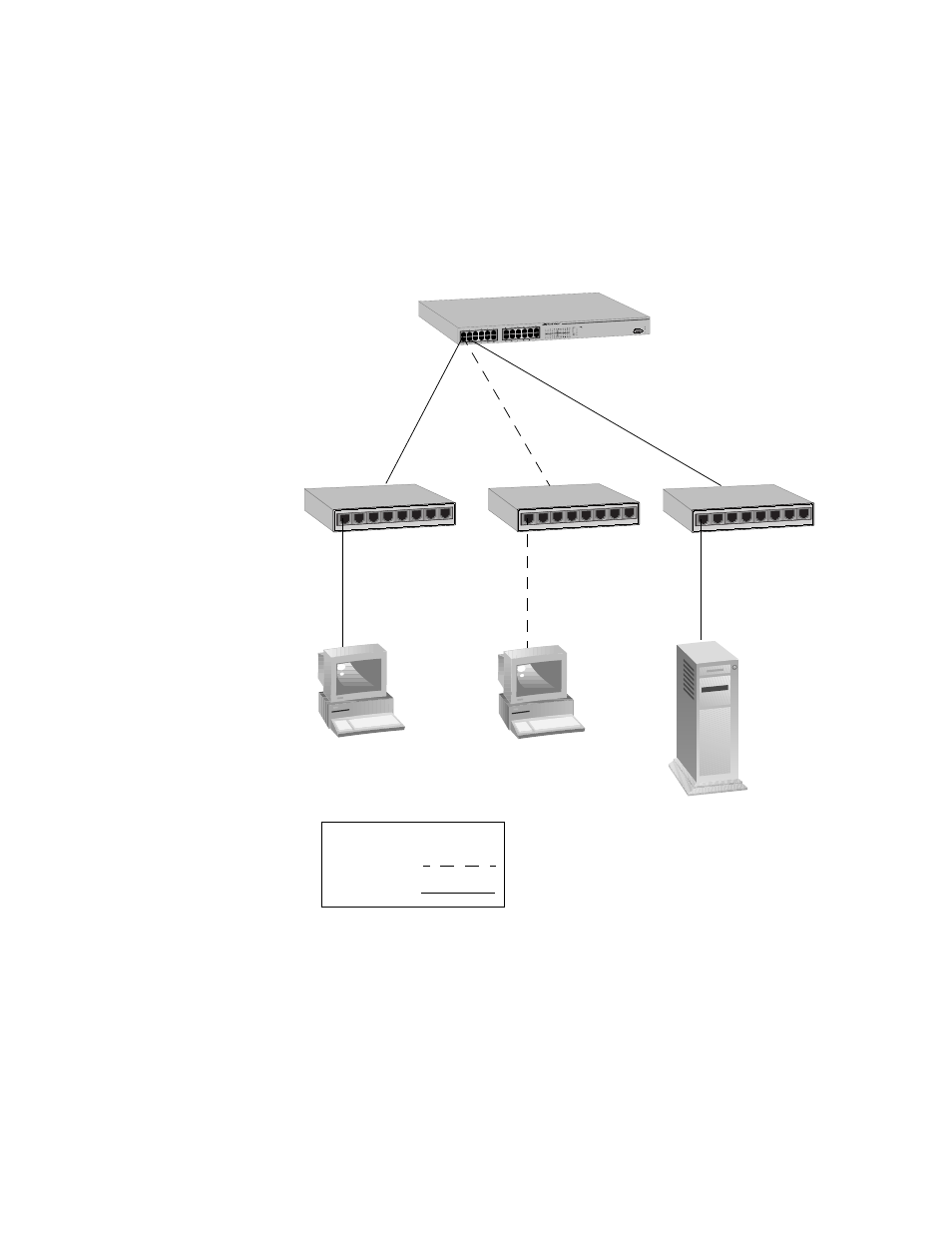
In the topology illustrated in Figure 15, an AT-8024 connects together
10/100 Mbps Ethernet hubs. This type of topology is often referred to as
a collapsed backbone topology. The switch functions as the focal point
of the network by acting as a bridge between the different workgroups.
The switch transfers an Ethernet frame from hub to hub only when the
destination end-node for the frame is on a different hub than the end-
node that originated the frame. This reduces the amount of unnecessary
data traffic in each workgroup, freeing up bandwidth and improving
network performance.
Figure 15. Collapsed Backbone - Hub Topology
Link
Mode
Link
Mode
100
FULL
ACT
MODE
COL
FAULT
MASTER
PWR
AT-8024
10Base-T / 100Base-TX F
ast Ethernet Switch
RS-232 TERMINAL PO
RT
5
4
3
2
1
6
7
8
5
4
3
2
1
6
7
8
5
4
3
2
1
6
7
8
Legend
10 Mbps
100 Mbps
AT-8024 Fast
Ethernet Switch
Ethernet
Hubs