ADT Security Services ADT-UDACT User Manual
Page 60
Document 50934 Rev B 5/15/00 PN 50934:B
60
Notes:
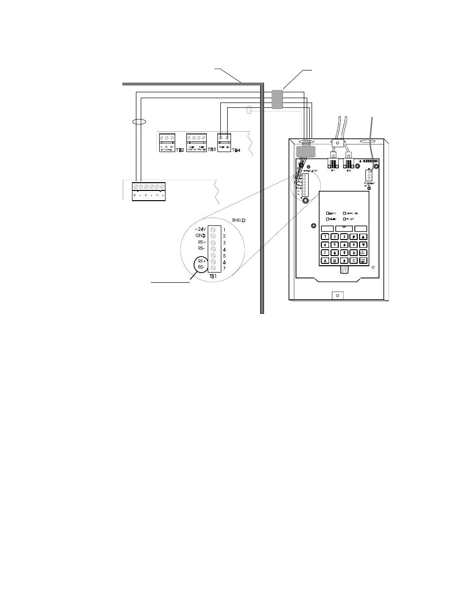
1) Ferrite cores are recommended for all applications.
2) Recommended wire is 12 AWG to 18 AWG twisted pair.
3) Shielded wire is not required (unless mandated by local AHJ).
If shielded wire is used, connect only one end of shield:
a) shield may be connected to cabinet (earth ground) at fire alarm panel, or
b) shield may be connected to TB1 Terminal 5 (Shield) at ADT-UDACT as shown in Figure E-3.
NOTE: The shield end that is not connected should be insulated to prevent accidental grounding.
Do not connect both ends of shield under any circumstance since a ground fault may result.
4) Conduit is recommended for external wire runs. Consult local building codes.
5) Connect Ground Strap (supplied with ADT-ABS8RF enclosure) from Earth Ground terminal on ADT-
UDACT to a solid building earth ground. Conduit alone will not provide a reliable earth ground.
6) ADT-UDACT may be located up to 6,000 feet away from the host control panel.
7) Refer to Specifications for power requirements.
EIA-485 (ACS Mode)
TB4-1 (+)
TB4-2 (–)
MPS-400
ADT-CPU-400
TB2-1 (+)
TB2-2 (–)
24 VDC
Nonresettable
power
Ferrite cores
PN 29090
Unimode 400 Cabinet
Install 120 watt EOL
resistor (PN: 71244) on
TB1 terminals 3 and 4 if
last or only device on
EIA-485 line
Supervised and
Power-limited
EIA-485 and
power wiring
To supervised
phone lines
Solid earth
ground
ADT-UDACT in ADT-ABS8RF
(shown with cover removed)
DO NOT USE
Figure E-3: Unimode 400 External ADT-UDACT Mounting in ADT-ABS8RF