0 installation and wiring, Figure 2-1: wiring phone jacks, 2 output circuits 2.1 general – ADT Security Services ADT-UDACT User Manual
Page 14
Document 50934 Rev B 5/15/00 PN 50934:B
14
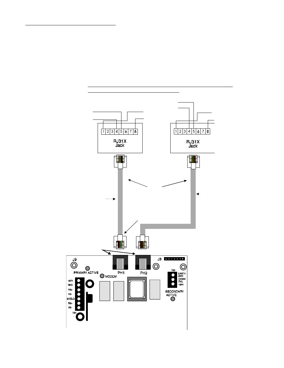
Figure 2-1: Wiring Phone Jacks
Note: Shorting bars
inside RJ31X Jack
removed during male
plug insertion
7 foot
Cable
(MCBL-7)
Order Separately
Green Wire
Green Wire
Red Wire
Red Wire
To premise phones
To premise phones
Tip
Ring
Ring
Tip
Primary
Phone Line
PH-1
Secondary
Phone Line
PH-2
Modular Female
Connectors
Male Plug
Connectors
Tip
Ring
Ring
Tip
(Primary
Lines)
Incoming
Telco Phone
Lines
(Secondary Lines)
Incoming Telco
Phone Lines
Mounting Options
For information on mounting the ADT-UDACT in a specific fire alarm control panel,
refer to the appropriate Appendix.
Telephone Circuits
Provision to connect to two independent telephone lines is available via two
telephone jacks labeled PH1 (Primary) and PH2 (Secondary). Telephone line control/
command is possible via double line seizure as well as usage of an RJ31X style
interconnection. (RJ31X jacks must be ordered separately).
Note: It is critical that the ADT-UDACT be located as the first device on the
incoming telephone circuit to properly function.
2.2
Output Circuits
2.1
General
2.0 Installation and Wiring
UDACJAKN.WMF