Collapsed backbone – Allied Telesis AT-FS750/48 User Manual
Page 27
AT-FS750/48 Fast Ethernet Smart Switch Installation Guide
27
Collapsed
Backbone
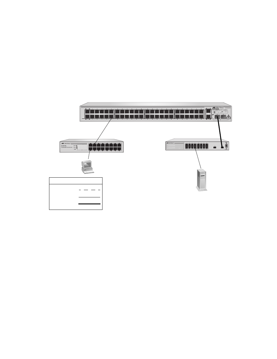
In the topology illustrated in Figure 7, an AT-FS750/48 Fast Ethernet
Smart switch connects switches that have Fast Ethernet uplinks. This type
of topology is often referred to as a collapsed backbone topology. The
switch functions as the focal point of the network and transfers an Ethernet
frame between the Fast Ethernet switches only when the destination end
node for the frame is on a different switch than the end node that
originated the frame. This reduces the amount of unnecessary data traffic
in each workgroup, freeing up bandwidth and improving network
performance.
Figure 7. Collapsed Backbone - Hub Topology
LINK/ACT
SPEED
LINK/ACT
SPEED
POWER
15
16
LINK/ACT
1
3
5
7
9
11
13
15
2
4
6
8
10
12
14
16
AT-GS950/16
16-Port 10/100/1000Mbps + 2 SFP Combo WebSmart Switch
731
Legend
100 Mbps
1000 Mbps
10 Mbps
AT-FS716L
AT-GS950/16
1025
LINK
1000M
ACT
10M
100M
PORT ACTIVITY
100M
10M
- AT-GS908M (54 pages)
- AT-x230-10GP (80 pages)
- AT-GS950/10PS (386 pages)
- AT-GS950/48PS (64 pages)
- AT-GS950/16PS (386 pages)
- AT-GS950/48PS (386 pages)
- AT-9000 Series (1480 pages)
- AT-9000 Series (258 pages)
- IE200 Series (70 pages)
- AT-GS950/48 (410 pages)
- AT-GS950/8 (52 pages)
- AT-GS950/48 (378 pages)
- AT-GS950/48 (60 pages)
- SwitchBlade x8106 (322 pages)
- SwitchBlade x8112 (322 pages)
- SwitchBlade x8106 (240 pages)
- SwitchBlade x8112 (240 pages)
- AT-TQ Series (172 pages)
- AlliedWare Plus Operating System Version 5.4.4C (x310-26FT,x310-26FP,x310-50FT,x310-50FP) (2220 pages)
- FS970M Series (106 pages)
- 8100L Series (116 pages)
- 8100S Series (140 pages)
- x310 Series (120 pages)
- x310 Series (116 pages)
- AT-GS950/24 (404 pages)
- AT-GS950/24 (366 pages)
- AT-GS950/16 (44 pages)
- AT-GS950/16 (364 pages)
- AT-GS950/16 (404 pages)
- AT-GS950/8 (404 pages)
- AT-GS950/8 (364 pages)
- AT-GS950/8 (52 pages)
- AT-8100 Series (330 pages)
- AT-8100 Series (1962 pages)
- AT-FS970M Series (330 pages)
- AT-FS970M Series (1938 pages)
- SwitchBlade x3106 (288 pages)
- SwitchBlade x3112 (294 pages)
- SwitchBlade x3106 (260 pages)
- SwitchBlade x3112 (222 pages)
- AT-S95 CLI (AT-8000GS Series) (397 pages)
- AT-S94 CLI (AT-8000S Series) (402 pages)
- AT-IMC1000T/SFP (23 pages)
- AT-IMC1000TP/SFP (24 pages)
- AT-SBx3106WMB (44 pages)