Sfp leds – Allied Telesis AT-FS750/48 User Manual
Page 21
AT-FS750/48 Fast Ethernet Smart Switch Installation Guide
21
SFP LEDs
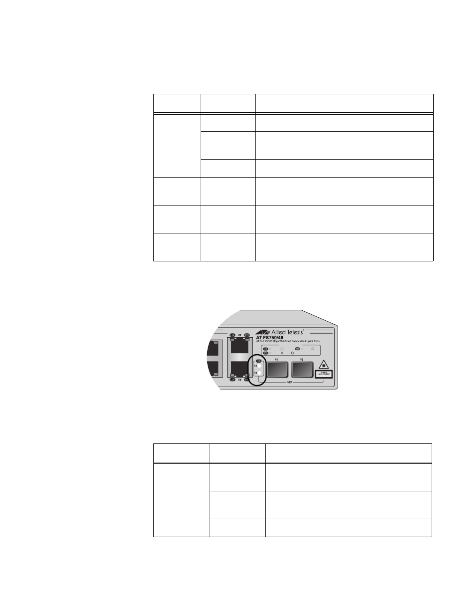
Each SFP port, ports 51 and 52, has one LED as shown in Figure 5 and
described in Table 5 on page 21.
Figure 5. SFP LED
Table 4. 10/100/1000Base-T Port LEDs
LED
State
Description
L/A
Green
A valid link has been established on the port.
Blinking
Green
The port is transmitting or receiving data.
Off
No link is established on the port.
SPD
Green
A valid 1000 Mbps link is established
between the uplink port and the end node.
Amber
A valid 100 Mbps link is established between
the uplink port and the end node.
Off
A valid 10 Mbps link is established between
the uplink port and the end node.
1030
LINK
1000M
ACT
10M
100M
PORT ACTIVITY
100M
10M
Table 5. SFP LED
LED
State
Description
L/A
Green
A valid link has been established on the
port.
Blinking
Green
The port is transmitting or receiving data.
Off
No link is established on the port.
- AT-GS908M (54 pages)
- AT-x230-10GP (80 pages)
- AT-GS950/48PS (64 pages)
- AT-GS950/10PS (386 pages)
- AT-GS950/16PS (386 pages)
- AT-GS950/48PS (386 pages)
- AT-9000 Series (258 pages)
- AT-9000 Series (1480 pages)
- IE200 Series (70 pages)
- AT-GS950/48 (410 pages)
- AT-GS950/8 (52 pages)
- AT-GS950/48 (378 pages)
- AT-GS950/48 (60 pages)
- SwitchBlade x8106 (322 pages)
- SwitchBlade x8112 (322 pages)
- SwitchBlade x8106 (240 pages)
- SwitchBlade x8112 (240 pages)
- AT-TQ Series (172 pages)
- AlliedWare Plus Operating System Version 5.4.4C (x310-26FT,x310-26FP,x310-50FT,x310-50FP) (2220 pages)
- FS970M Series (106 pages)
- 8100L Series (116 pages)
- 8100S Series (140 pages)
- x310 Series (116 pages)
- x310 Series (120 pages)
- AT-GS950/24 (404 pages)
- AT-GS950/24 (366 pages)
- AT-GS950/16 (44 pages)
- AT-GS950/16 (404 pages)
- AT-GS950/16 (364 pages)
- AT-GS950/8 (404 pages)
- AT-GS950/8 (364 pages)
- AT-GS950/8 (52 pages)
- AT-8100 Series (330 pages)
- AT-8100 Series (1962 pages)
- AT-FS970M Series (330 pages)
- AT-FS970M Series (1938 pages)
- SwitchBlade x3106 (288 pages)
- SwitchBlade x3112 (294 pages)
- SwitchBlade x3106 (260 pages)
- SwitchBlade x3112 (222 pages)
- AT-S95 CLI (AT-8000GS Series) (397 pages)
- AT-S94 CLI (AT-8000S Series) (402 pages)
- AT-IMC1000T/SFP (23 pages)
- AT-IMC1000TP/SFP (24 pages)
- AT-SBx3106WMB (44 pages)