Rd y, Class 1 lase r p ro duc t – Allied Telesis AT-CV1000 User Manual
Page 27
AT-CV1000 One-Slot Chassis Installation Guide
27
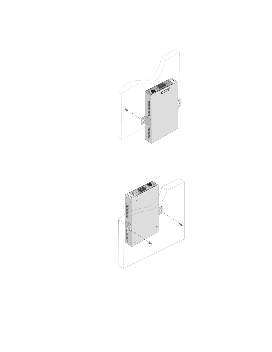
6. Install two plastic anchors and two screws onto the wall, as illustrated
in Figure 9.
Figure 9. Installing the Plastic Anchors and Screws Onto the Wall
7. Position the chassis vertically onto the wall screws, as illustrated in
Figure 10, and slide it down to secure the brackets against the wall.
Figure 10. Positioning The AT-CV1000 Chassis Onto the Wall Screws
8. Cable the line card according to the instructions that were shipped with
the line card.
9. Power on the chassis according to the instructions in “Powering On an
AT-CV1000 Chassis” on page 35..
AT
-CM202
LK
AT
S
F
P
LK
A
T F
D
AT
-C
V1
00
0
SM
L M
L OA
M
T
X
RD
Y
295
CLASS
1
LASE
R P
RO
DUC
T
40-60VDC INP
UT
AT
-C
M2
02
LK
A
T
LK A
T FD
SML ML
OA
M
RDY
A T
-C
V1
00
0
296
See also other documents in the category Allied Telesis Computer hardware:
- AT-GS908M (54 pages)
- AT-x230-10GP (80 pages)
- AT-GS950/10PS (386 pages)
- AT-GS950/48PS (64 pages)
- AT-GS950/16PS (386 pages)
- AT-GS950/48PS (386 pages)
- AT-9000 Series (1480 pages)
- AT-9000 Series (258 pages)
- IE200 Series (70 pages)
- AT-GS950/48 (410 pages)
- AT-GS950/8 (52 pages)
- AT-GS950/48 (378 pages)
- AT-GS950/48 (60 pages)
- SwitchBlade x8112 (322 pages)
- SwitchBlade x8106 (322 pages)
- SwitchBlade x8106 (240 pages)
- SwitchBlade x8112 (240 pages)
- AT-TQ Series (172 pages)
- AlliedWare Plus Operating System Version 5.4.4C (x310-26FT,x310-26FP,x310-50FT,x310-50FP) (2220 pages)
- FS970M Series (106 pages)
- 8100L Series (116 pages)
- 8100S Series (140 pages)
- x310 Series (116 pages)
- x310 Series (120 pages)
- AT-GS950/24 (404 pages)
- AT-GS950/24 (366 pages)
- AT-GS950/16 (44 pages)
- AT-GS950/16 (364 pages)
- AT-GS950/16 (404 pages)
- AT-GS950/8 (404 pages)
- AT-GS950/8 (364 pages)
- AT-GS950/8 (52 pages)
- AT-8100 Series (330 pages)
- AT-8100 Series (1962 pages)
- AT-FS970M Series (330 pages)
- AT-FS970M Series (1938 pages)
- SwitchBlade x3106 (288 pages)
- SwitchBlade x3112 (294 pages)
- SwitchBlade x3106 (260 pages)
- SwitchBlade x3112 (222 pages)
- AT-S95 CLI (AT-8000GS Series) (397 pages)
- AT-S94 CLI (AT-8000S Series) (402 pages)
- AT-IMC1000T/SFP (23 pages)
- AT-IMC1000TP/SFP (24 pages)
- AT-SBx3106WMB (44 pages)