Connecting the frame ground wire – Allied Telesis AT-MCR12 User Manual
Page 42
Chapter 2: Installation
42
.
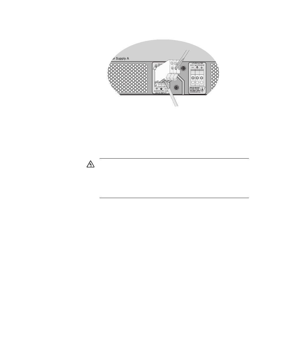
Figure 18. Connecting the Frame Ground Wire
5. Connect the positive feed wire to the terminal block marked +
(positive).
6. Connect the negative feed wire to the terminal block marked -
(negative).
7. Secure the tray cable near the rack framework using multiple cable
ties (not provided) to minimize the chance of the connections being
disturbed by casual contact with the wiring. Allied Telesis recommends
that you use at least four cable ties 10 centimeters (4 inches) apart
with the first one located within 15 centimeters (6 inches) of the
terminal block.
8. Ensure that the circuit breaker is in the Off position.
9. Connect the DC wires to the circuit breaker.
10. Power on the circuit breaker.
11. Verify that the Power LED is green. If it is not, refer to Chapter 3,
Warning: Check to see if there are any exposed copper strands
coming from the installed wire. When this installation is done
correctly there should be no exposed copper wire strands
extending from the terminal block. Any exposed wiring can
conduct harmful levels of electricity to persons touching the
wires.
E12