Auxiliary power supply slot, Figure 3. back panels – Allied Telesis AT-MCR12 User Manual
Page 17
AT-MCR12 Media Conversion Rack-Mount Chassis Installation Guide
17
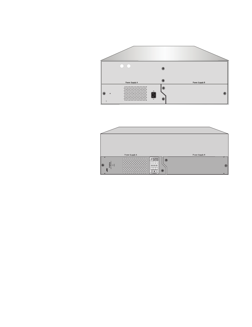
Figure 3 shows the back panels of the AC and DC versions of the chassis
as they are shipped with one power supply in slot A.
Figure 3. Back Panels
Auxiliary Power
Supply Slot
The AT-MCR12 chassis is shipped with one AT-PWR4 (AC) or AT-PWR9
(DC) power supply installed in slot A, with slot B for an auxiliary power
supply.
The power supply provides automatic load balancing for one or two power
supplies. If a power supply fails, the green power LED on the front of the
AT-MCR12 chassis goes out, and the entire power load is shifted to the
auxiliary power supply unit. The power supplies are hot-swappable.
For detailed information on the features and specifications of the
AT-PWR4 power supply, refer to the AT-PWR4 Power Supply Installation
Guide. Information about the features and specifications of the AT-PWR9
power supply is available in the AT-PWR9 Power Supply Installation
Guide.
Figure 4 shows the rear view of the AT-MCR12 rack-mount chassis with
C
e
n
tr
eC
O
M
P
W
R
4
PO
WER
1269
1285
Power Supply Slot A
Auxiliary Power Supply Slot B
AC Model
DC Model
Power Supply Slot A
Auxiliary Power Supply Slot B