Figure 22. stripped wire – Allied Telesis AT-MCR12 User Manual
Page 41
AT-MCR12 Media Conversion Rack-Mount Chassis Installation Guide
41
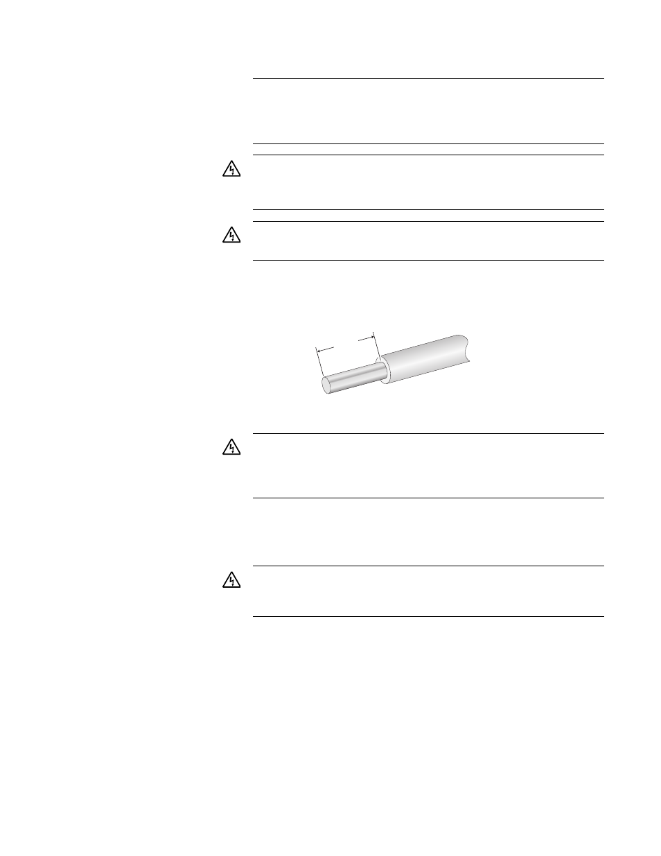
3. With a 14-gauge wire-stripping tool, strip the three wires in the tray
cable coming from the DC input power source to 8 millimeters ± 1
millimeters (0.31 inches ± 0.039 inches), as shown in Figure 17.
Figure 17. Stripped Wire
4. Connect the frame ground wire to the terminal marked with the ground
symbol by inserting the wire into the terminal block and tightening the
connection with a flathead screwdriver, as shown in Figure 18.
A tray cable is required to connect the power source if the unit is
powered by centralized DC power. The tray cable must be UL
listed Type TC tray cable and rated at 600 V and 90 degrees C,
with three conductors, minimum 14 AWG.
E24
Warning: Circuit breaker is used as a disconnection device. To
de-energize equipment, shut down the circuit breaker and then
disconnect the input wire.
E38
Warning: DC input shall be from a secondary source isolated
from the mains by reinforced insulation.
8mm ±1mm
(0.31in. ±0.039in.)
Warning: Do not strip more than the recommended amount of
wire. Stripping more than the recommended amount can create
a safety hazard by leaving exposed wire on the terminal block
after installation.
E10
Warning: When installing this equipment, always ensure that the
frame ground connection is installed first and disconnected last.
E11