Powering on the provider unit – Allied Telesis AT-МС602 User Manual
Page 33
Installation
33
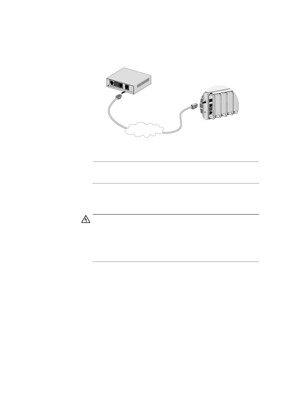
3. Next, connect a telephone line cable from the VDSL Line port to the
wall/interior telephone line, as shown in Figure 22, so that the Provider
unit can communicate with the Subscriber unit.
Figure 22 VDSL Line to Wall/Interior Phone Line
Note
The procedure for connecting the management cable is described in
”Cabling Preparations” on page 36.
Powering On the
Provider Unit
Powering on the AT-MC602 Provider Unit requires that the host
equipment, AT-MCR12 rackmount chassis, is powered on as well.
Warning
The QUALIFIED SERVICE PERSONNEL must verify that the
AT-MCR12 power cord is connected to the socket provided with the
ground conductor.
If the power cord is not connected, the QUALIFIED SERVICE
PERSONNEL must install a permanent ground connection using the
bond stud on the rear panel of the AT-MCR12 chassis.
For detailed information on how to power on the AT-MCR12 unit, refer to
the AT-MCR12 Media Converter Rackmount Chassis Installation Manual.
MCR12
LINE
10
B
as
eT
/
100Base
TX
LINK
AC
T
PWR
ERR
LINK
MGMT
AT
-MC602
VDSL EXTENDED ETHERNET
PSTN
LINE
10BaseT/
100BaseT
X
PSTN
LINK
ACT
PWR
ERR
LINK
MGMT
AT-MC601
VDSL EX
TENDED
ETHER
NET
Wall/Interior Phone Line