Installing the switch in a rack, Chapter 2: installation 30 – Allied Telesis AT-FS724L User Manual
Page 30
Chapter 2: Installation
30
Installing the Switch in a Rack
Perform the following procedure to install either switch in a standard
19-inch rack. Two rack mounting brackets and eight mounting screws are
provided for attachment to your switch.
1. Remove any data cables and the power cord from the switch if they
are attached to the switch.
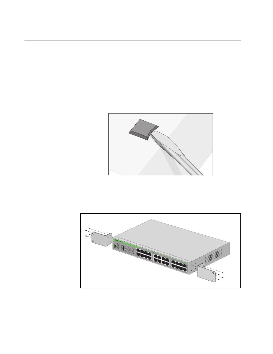
2. If attached, remove the rubber feet from the bottom of the chassis with
a flat bladed screw driver as shown in Figure 7.
Figure 7. Removing the Rubber Feet from Chassis
3. Attach the two mounting brackets (provided) to the sides of the switch
using the bracketmounting screws (provided), as shown in Figure 8.
Figure 8. Attaching Brackets for Rackmounting
1546
AT-FS
724L
24 Por
t Un
manag
ed F
ast Eth
ernet
Switch
1
3
5
7
9
11
13
15
17
19
21
23
2
4
6
8
10
12
14
16
18
20
22
24
18
20
22
24
10
12
14
16
2
4
6
8
9
11
13
15
1
3
5
7
17
19
21
23
POWE
R
10 LIN
K
ACT
100 L
INK
ACT
FDX
HDX
COL