Cascade topology – Allied Telesis AT-FS724L User Manual
Page 21
AT-FS716L & AT-FS724L Fast Ethernet Switch Installation Guide
21
Cascade
Topology
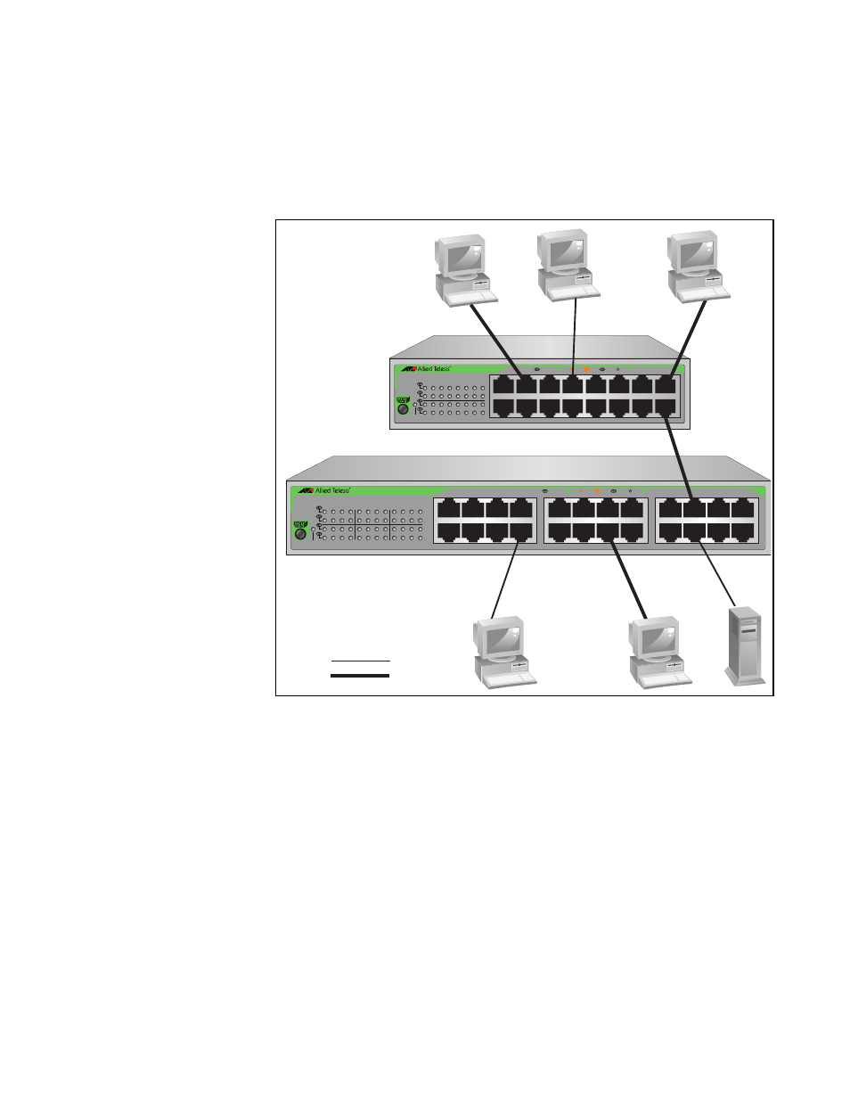
Connecting two similar networking devices together is called “cascading.”
Figure 5 illustrates this topology where Port 19 on the AT-FS724L switch is
connected to Port 16 on the AT-FS716 switch. Since the ports are
configured as auto MDI/MDI-X, a crossover or straight-through Category 5
or better twisted-pair cable can be used in any of the ports.
Figure 5. Cascade Topology
AT-FS724L
24 Port Unmanaged Fast Ethernet Switch
1
3
5
7
9
11
13
15
17
19
21
23
2
4
6
8
10
12
14
16
18
20
22
24
18
20
22
24
10
12
14
16
2
4
6
8
9
11
13
15
1
3
5
7
17
19
21
23
POWER
10 LINK
ACT
100 LINK
ACT
FDX
HDX
COL
AT-FS716L
16
Port Unmanaged Fast Ethernet Switch
1
3
5
7
9
11
13
15
2
4
6
8
10
12
14
16
POWER
10 LINK
ACT
100 LINK
ACT
FDX
HDX
COL
1
3
5
7
9
11
13
15
2
4
6
8
10
12
14
16
1538
10 Mbps
100 Mbps