Rear panel dip switches configuration, Table 7. rear panel dip switch settings – Allied Telesis AT-GS2002/SP User Manual
Page 34
Chapter 2: Installation
34
Rear Panel DIP Switches Configuration
Before the AT-GS2002/SP Media Converter is installed, the rear panel
DIP switches must be configured for the two Ethernet ports. The DIP
switch are numbered 1 - 4 and each one controls a specific function for a
specific port. The port numbers assigned to each DIP switch are clearly
marked the table on the rear panel. The specific switch functions are given
in Table 7 for the possible settings.
Note
The DIP switch location is shown in Figure 2 on page 19. Port 1
(SFP port) and Port 2 (twisted-pair port) are shown in Figure 1 on
page 19.
When setting the DIP switches, consider the following:
Setting the Auto Neg DIP switch for the twisted-pair port to ON or
OFF enables or disables Auto-Negotiation for the port. If you
disable Auto-Negotiation, be sure to set the DIP switches for the
port’s speed and duplex mode to match the speed and duplex
mode of the end-node device connected to the converter’s copper
port.
If you enable Auto-Negotiation, be sure that the end-node device is
also configured for Auto-Negotiation.
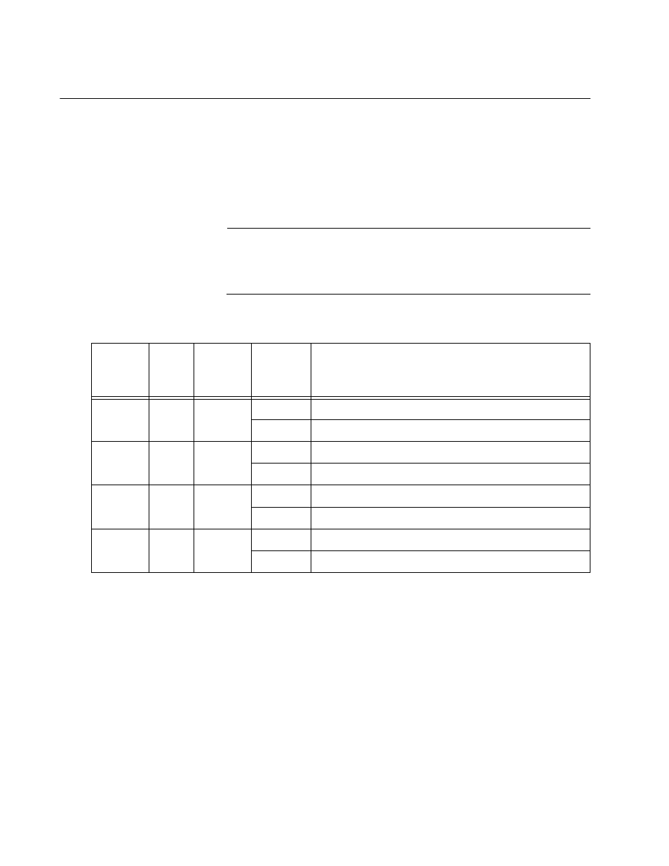
Table 7. Rear Panel DIP Switch Settings
DIP
Switch
Number
Port
Setting
Position
Description
1
2
AUTO
NEG
UP
Auto-negotiation on the twisted-pair port is OFF.
DOWN
Auto-negotiation on the twisted-pair port is ON.
2
2
SPEED
(Mbps)
UP
The twisted-pair port operates at 10 Mbps.
DOWN
The twisted-pair port operates at 100 Mbps.
3
2
DUPLEX
MODE
UP
The twisted-pair port operates in half-duplex mode.
DOWN
The twisted-pair port operates in full-duplex mode
4
1
SFP
UP
A 100Base-FX SFP module is installed.
DOWN
A 1000Base-X SFP module is installed.