Merlin, Installation – Maximum Merlin (pre-2001) User Manual
Page 2
MERLIN
INSTALLATION
(continued)
Samuel Barnett Boulevard
New Bedford, MA 02745
(508) 995-2200
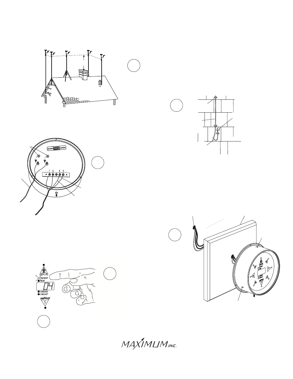
6
Follow the instructions supplied with the antenna
mount and secure the mast to the mount.
9
7
8
Feed the cables through the wall to where the read-out is going to
be located. Attach the wires to the rear of the read-out as shown.
The red wire from the direction sensor cable connects to terminal #4.
the green wire to terminal #5. Connect the black and white wires
from the speed sensor to terminals #1 and #2. The polarity does
not matter. Although the cable shield itself is not connected, shielded
cable must be used. Connect the wires from the AC adapter to the
meter. The polarity does not matter. (Do NOT adjust the nuts that
are already on the meter).
Mount the brass read-out directly over the cable feed-thru-hole
to avoid crimping the wire under the lip. We recommend mounting
the read-out on one of our pre-drilled and centered panels. Plug the
power supply into a 110 VAC power outlet.
8 FEET
CHIMNEY
MOUNT
VENT-PIPE
MOUNT
TRIPOD
MOUNT
WALL
MOUNT
EVE
MOUNT
CABLE-HOLE
WALL
Secure the wire to the building using cable clips (do not use regular
staples). Form a drip loop where the wires enter the hole drilled
through the exterior wall. Caulk the hole when done.
DRIP
LOOP
FROM AC
ADAPTER
BRASS
NUTS
CAULK
WIRE
CABLE
CLIPS
RED
WIRE
GREEN
WIRE
When Merlin first starts up it will
perform a brief self-test and then
go to the "Present" function mode.
Reset all memory functions (see operating instructions).
Resetting gives Merlin a fresh starting point for your
reference.
10
11
SCREW
SCREW
PANEL