Wesley BC-6200-8SA User Manual
Page 26
20
Curtis 1268 Manual,
Rev. D
THROTTLE 0%
The throttle 0% parameter defines the throttle input voltage at which a throttle
command begins. Voltages lower than the programmed value (but higher than
THRTL FAULT LO
) are interpreted to be in a 0% deadband.
THROTTLE 100%
The throttle 100% parameter defines the throttle input voltage that gives a full
throttle command. Input voltages above this value (but lower than
THRTL FAULT
HI
) are interpreted as 100% throttle command.
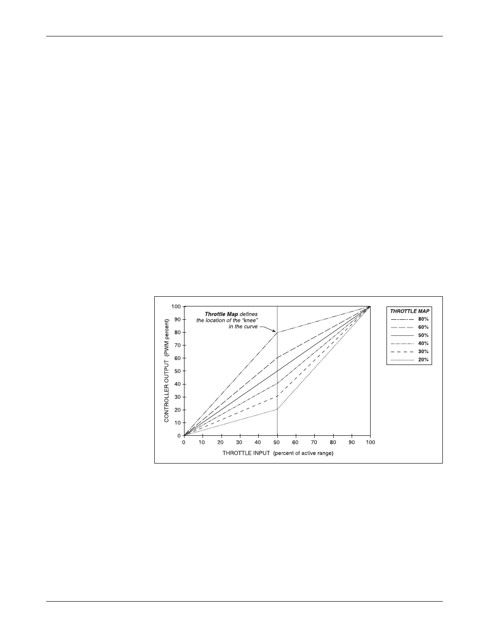
THROTTLE MAP
The throttle map parameter modifies the vehicle’s response to the throttle
input. As shown in Figure 7, this parameter determines the controller output
for a given amount of applied throttle. The
THROTTLE MAP
setting refers to the
controller output at half throttle, the midpoint of the throttle’s full active range
(the range between
THROTTLE 0%
and
THROTTLE 100%
).
3 — PROGRAMMABLE PARAMETERS: Throttle Parameters
Throttle Parameters
Fig. 7
Throttle maps for
controller with the Throttle
Map parameter set at vari-
ous values.
Setting
THROTTLE MAP
at 50% provides a linear output response to throttle
position. Values below 50% reduce the controller output at low throttle settings,
providing enhanced slow speed control. Values above 50% give the vehicle a
faster, jumpier feel at low throttle settings.
Controller output begins when the throttle is moved beyond
THROTTLE 0%
,
and continues to increase—following the curve defined by the
THROTTLE MAP
setting—as the throttle input increases, and reaches maximum output when
the throttle input crosses the
THROTTLE 100%
threshold.
- BC-6200-8CA BC-6000-8SA BC-6000-8CA BC-6200-8SAC BC-6250-8SA BC-6250-8CA BC-620-8SA BC-620-8CA BC-600-8SA BC-600-8CA BC-625-8SA BC-625-8CA SCT-7750-8AC SCT-7750-8SA SCT-7750-8CA SCT-7750-6AC SCT-7750-8AC-MTR SCT-7750-8CA-MTR PC-325-6SA PC-325-6CA PMT-5000-8CA PMT-5000-8SA PMT-4500-8SA PMT-4500-8CA SC-775-8CA SC-775-8SA SC-775-8AC