Preparing the tower for use, 1 enclosure, datalogger, power supply, 1 enclosure – Campbell Scientific UT20 and UT30 Tower-based Weather Stations User Manual
Page 30: Enclosure, datalogger, power supply, Enclosure, And li200x solar radiation sensor
UT20 and UT30 Tower-based Weather Stations
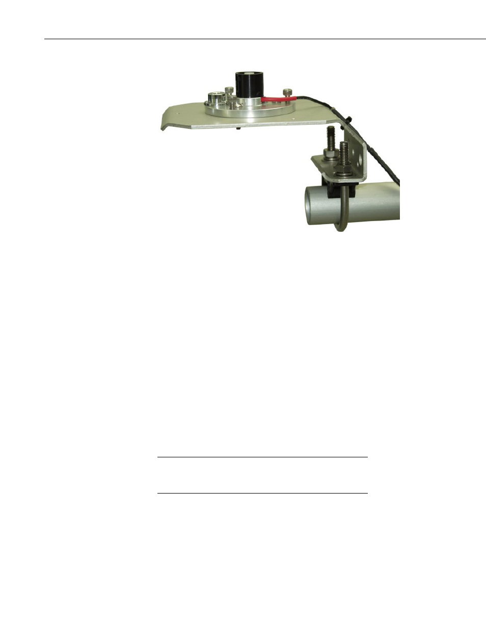
FIGURE 7-16. CM225 Solar Radiation Mount with a LI2003S Leveling
Base and LI200X Solar Radiation Sensor
8. Preparing the Tower for Use
8.1 Enclosure, Datalogger, Power Supply
8.1.1 Enclosure
All instrumentation (datalogger, power supply, and communication
peripherals) are mounted in the enclosure. A PVC bulkhead port is installed in
the enclosure for routing the sensor and communication cables to the
instrumentation.
The “-TM” option is used to attach our enclosures to a UT20 or UT30 tower.
An enclosure ordered with the “-TM” option will be shipped with a three-piece
bracket mounted to the top of the enclosure and an identical three-piece bracket
mounted to the bottom of the enclosure. This mounting bracket option uses the
same three-piece brackets as the “-MM” option, except the pieces are
rearranged so that the flanges are on the side of the bracket instead of in the
middle. The distance between the centers of each flange needs to be 17 inches
(see FIGURE 8-1, FIGURE 8-2, and FIGURE 8-3).
Enclosures with the “-TM” option are shipped configured for the
UT10 tower. Steps 1 through 3 of the following procedure are for
configuring the bracket for attachment to a UT20 or UT30 tower.
Attach the enclosure to a UT20 or UT30 tower as follows:
1. Remove the bolts and nuts connecting the bracket to the enclosure.
2. Slide out the flange sections so that the distance between the centers of
each flange is 17 inches (see FIGURE 8-1).
NOTE
20