Ut20/ut30 tower installation, 1 installing the ut20/ut30, 1 base and guy anchor layout – Campbell Scientific UT20 and UT30 Tower-based Weather Stations User Manual
Page 19: Installing the ut20/ut30, Base and guy anchor layout, 1. ut20/ut30 weather tower
UT20 and UT30 Tower-based Weather Stations
7. UT20/UT30 Tower Installation
7.1 Installing the UT20/UT30
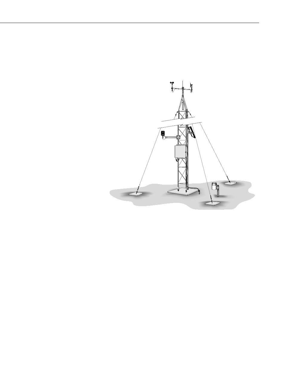
The UT20/UT30 tower provides a support structure for mounting the weather
station components. FIGURE 7-1 shows a typical UT20/UT30 equipped with
an instrumentation enclosure, meteorological sensors, and a solar panel.
FIGURE 7-1. UT20/UT30 weather tower
7.1.1 Base and Guy Anchor Layout
The UT20/UT30 tower attaches to a user-supplied concrete foundation as
shown in FIGURE 7-1. The base brackets, anchor bolts, and nuts are included
with the tower.
A guyed UT20 tower requires an area approximately 11.5 feet in radius, and a
guyed UT30 tower requires an area approximately 17 feet in radius. Brush and
tall weeds need to be removed. Otherwise, the natural vegetation and ground
surface should be disturbed as little as possible.
Drive a stake where the base of the tower will be located. Attach a line to the
stake and scribe a circle with an 11.5 foot radius for the UT20 or a 17 foot
radius for the UT30. Drive a stake on the scribed line opposite the direction
the tower will hinge for the first guy anchor location (FIGURE 7-2).
When using a UT30 on level ground, lay out the remaining two anchor
locations by measuring 29.5 feet from the first anchor to the scribed line on
either side of the base stake (FIGURE 7-2). When using a UT20 on level
9