5 connect, 3 tcp serial server, 1 physical setup – Campbell Scientific NL240 Wireless Network Link Interface User Manual
Page 32: 2 configuring the nl240, Connect, Tcp serial server, Physical setup, Configuring the nl240, 2. bridge mode loggernet setup
NL240 Wireless Network Link Interface
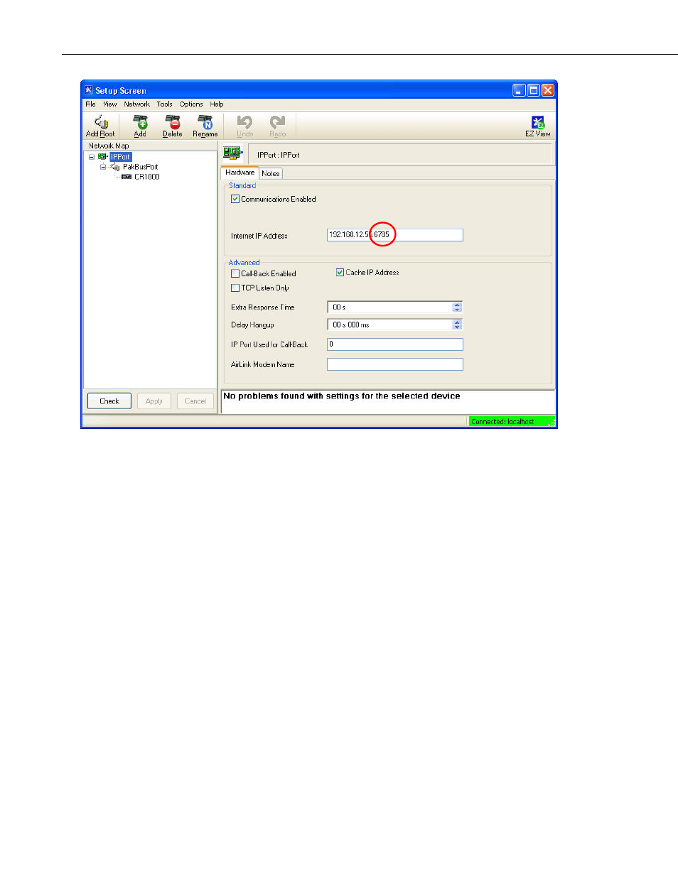
FIGURE 8-2. Bridge mode LoggerNet setup
8.2.2.5 Connect
You are now ready to connect to your datalogger using the LoggerNet Connect
screen.
8.2.3 TCP Serial Server
The NL240 can tunnel RS-232 and CS I/O serial communications over Wi-Fi.
Any packet sent to the configured IP port will have the IP layer removed, and
the data is then directed to the serial connection.
8.2.3.1 Physical Setup
Using the supplied serial cable, connect the NL240 CS I/O port or RS-232 port
to the datalogger CS I/O or RS-232 port, respectively. The NL240 will be
powered if connected via CS I/O. Alternatively, power the NL240 through the
barrel-connector jack located on the edge of the device. Connect the NL240 to
your local wireless network by attaching an antenna to the NL240 WLAN
connector. Ensure that the device is powered up by inspecting the Power LED.
8.2.3.2 Configuring the NL240
RS-232 Serial Server
•
Connect to the NL240 in DevConfig (see Section 7, Configuring the
NL240).
22