Campbell Scientific CNR4 Net Radiometer User Manual
Page 23
CNR4 Net Radiometer
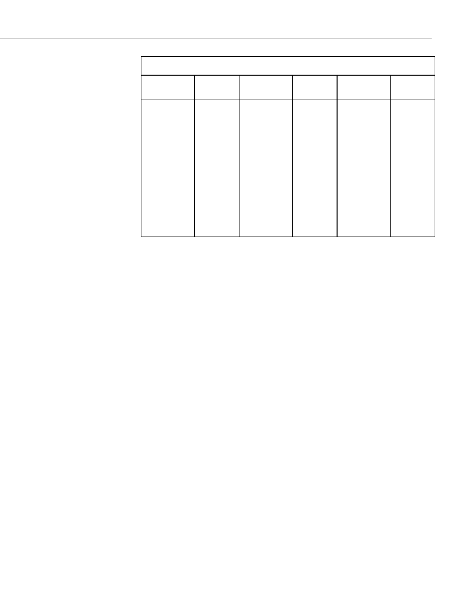
TABLE 7-1. Resistance values versus CNR4’s thermistor temperature in °C.
Temperature
[
°C]
Resistance
[
Ω]
Temperature
[
°C]
Resistance
[
Ω]
Temperature
[
°C]
Resistance
[
Ω]
–13
–12
–11
–10
–9
–8
–7
–6
–5
–4
–3
–2
–1
55170
52480
49940
47540
45270
43110
41070
39140
37310
35570
33930
32370
30890
17
18
19
20
21
22
23
24
25
26
27
28
29
13900
13330
12790
12260
11770
11290
10840
10410
10000
9605
9227
8867
8523
47
48
49
50
51
52
53
54
55
56
57
58
59
4331
4179
4033
3893
3758
3629
3504
3385
3270
3160
3054
2952
2854
Relatively small errors occur when the CNR4 is not in thermal equilibrium.
This happens for example when the heater is on, or when the sun is shining.
When the heater and ventilator are on, the largest expected deviation between
the real sensor temperature and the thermistor reading is 1 degree. This results
in a worst case error for the pyrgeometer of 5 W/m
2
. When the sun is shining,
the largest expected deviation between the real sensor temperature and the
thermistor reading is again 1 degree. This results in a worst case error for the
pyrgeometer of 5 W/m
2
.
The thermistor will not give a good indication of ambient air temperature; at
1000 W/m
2
solar radiation, and no wind, the instrument temperature will rise
approximately 5 degrees above the ambient temperature.
The offsets of both the pyranometers and the pyrgeometers might be larger
than 5 W/m
2
if large temperature gradients are forced on the instrument (larger
than 5 K/hr); for example, when rain hits the instrument. This occurrence can
be detected using the thermistor readout, and can be used for data filtering.
The thermistor measurement is calculated by the datalogger, using the Half-
Bridge Measurement instruction, which requires one voltage excitation and
one single-ended analog channel.
Alternatively, you can use the Pt-100 to make the temperature measurement.
In order to make the temperature measurement, using the Pt-100 sensor, you
will need one current excitation channel, and one differential analog channel.
TABLE 7–2 shows the Pt-100 resistance values as a function of temperature.
Please refer to Appendix C, CR3000 Program for Measuring Pt-100
Temperature Sensor, for a sample program to measure Pt-100.
15