3 cellular transceivers, Cr1000 – Campbell Scientific CM6/CM10 Tripod Weather Station Installation User Manual
Page 32
Section 3. Instrumentation Installation
SE
1
2
3
4
5
6
7
8
H
1
2
3
4
L
DIFF
H
EX1
H
L
H
L
L
P2
P1
12V
G
DC ONLY
CAUTION
LUG
GROUND
POWER IN
WIRING PANEL
CR1000
PERIPHERAL PORT
RS-232 (Not Isolated)
SN:
CS I/O
MADE IN USA
11
10
9
SE
15 16
13 14
12
H
L
DIFF
H
EX2
H
L
H
L
L
EX3
5
6
7
8
SW-12
5V
12V
12V
C5
C4
G
G
G
G
C1
C2
C3
G
G
C6
C7
C8
Tx
COM1
Rx Tx Rx
Tx Rx Tx Rx
COM2
COM3
COM4
POWER OUT
SDM
G 12V
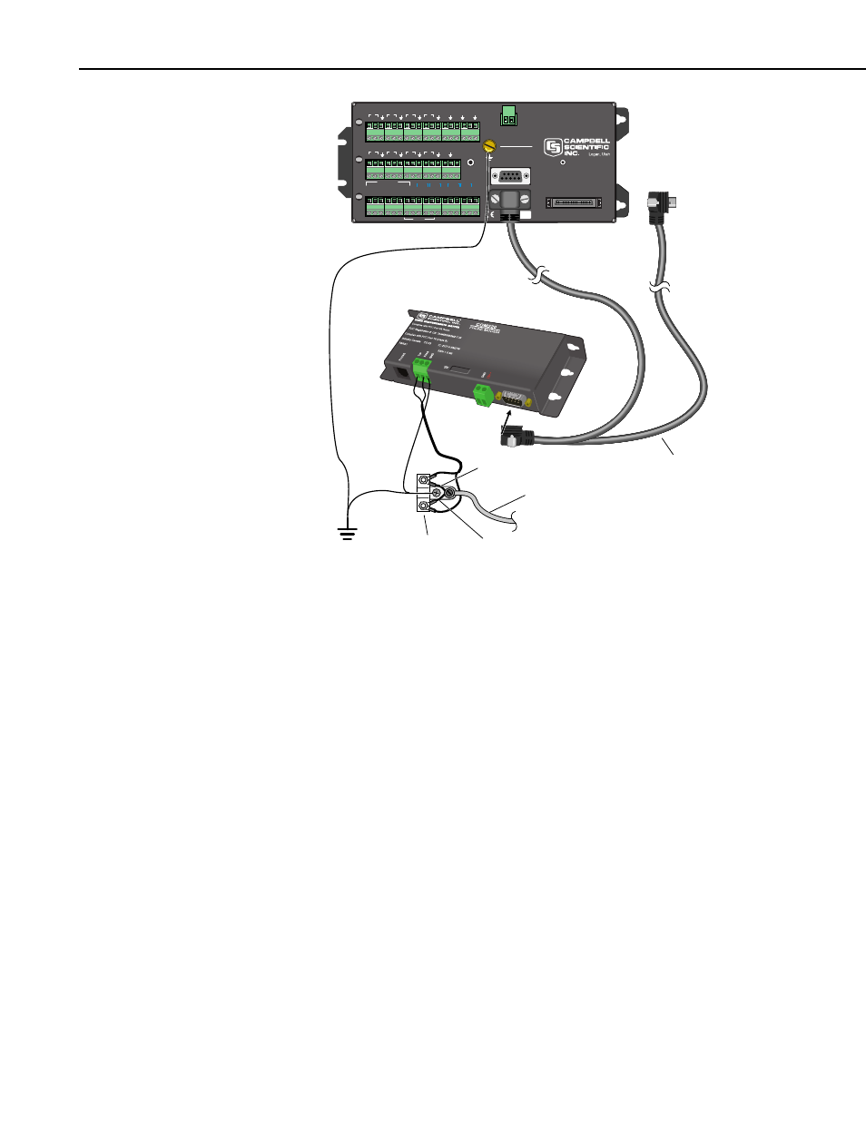
Burial Phone Cable
Blue = Ring
Blue/White = Tip
Phone Line
Transient Protector
(Model 6362 or 2372-01)
SC12 Cable
Earth
Ground
FIGURE 3.3-2. COM220 Modem with Surge Protector
3.3.3 Cellular Transceivers
Campbell Scientific offers two digital cellular modems—the RavenXTV
CDMA modem and the RavenXTG GPRS modem. Refer to our product
brochure for information on choosing the right cellular modem for your
weather station.
Mount the digital cellular modem in the enclosure by doing the following
steps:
1. Mount the modem to the enclosure backplate using the hardware provided
in the #14394 Mounting Kit.
2. Connect the modem to the datalogger’s CS I/O port via the SC105 or
SC932A interface or connect the modem to the datalogger’s RS-232 port
via the #14392 Null Modem Cable.
3. Mount the cellular antenna on a grounded mast, positioning it to point
toward the nearest cellular tower, with the radiating elements oriented
vertically. Route the coaxial cable into the enclosure through the wiring
port and connect it to the cellular transceiver’s coaxial connector. Provide
strain relief for the cable on the left side of the enclosure with a cable tie
and tab.
3-8