Datalogger to am25t wiring – Campbell Scientific AM25T 25-Channel Solid State Multiplexer User Manual
Page 9
AM25T Solid State Multiplexer
U-bolts are used to attach the enclosures to a 1.25" NPT pipe. The enclosure
may also be lag-bolted to a wall or similar flat surface.
Fasten the AM25T to the enclosure backplate. Securely fasten the leads to the
strain relief flange running between the AM25T terminal strips and install the
cover to reduce temperature gradients during thermocouple measurements.
3. Datalogger to AM25T Wiring
When powering the AM25T from the same battery as the datalogger, connect
the datalogger to the AM25T as shown in Table 3-1. Two CABLE4CBL-L
cables typically carry control, power, and measurement signals between the
AM25T and the datalogger.
Do not reverse the polarity of the +12 Volt and Ground
leads. Damage to the multiplexer, sensors, and
datalogger will occur.
WARNING
A separate battery can be used to power the AM25T. A separate battery might
be used when the AM25T is installed some distance from the datalogger.
Ground must be connected between the datalogger and the AM25T (Figure 2).
When leads in excess of 152 m (500 feet) are used to connect the datalogger to
the AM25T, it may be necessary to compensate for the drop in RTD excitation
voltage (program example 4).
All AM25T inputs are spark gap protected. To ensure that
the spark gaps fire, the large ground wire between the
AM25T and datalogger must not be greater than 152 m
(500 ft). In applications where lightning protection is not
required, limit the cable length between the AM25T and
datalogger to 305 m (1000 ft).
Caution
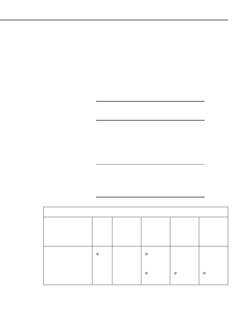
TABLE 3-1. Datalogger to AM25T Wiring
Function
AM25T
CR10(X)
21X/CR7
CR23X
CR800,
CR850,
CR1000,
CR3000,
CR5000,
CR9000X
+12V Power
12 V
12 V
12 V
12 V
12 V
Power and Shield Ground
G
G G
Clock
CLK
Control Port
Control Port
Control Port
Control Port
Reset
RES
Control Port
Control Port
Control Port
Control Port
RTD
Excitation
EX Excitation Excitation Excitation Excitation
Analog Ground
AG
AG
Common High
HI
Diff. Chan. H
Diff. Chan. H
Diff. Chan. H
Diff. Chan. H
Common Low
LO
Diff. Chan. L
Diff. Chan. L
Diff. Chan. L
Diff. Chan. L
5