Sensor to am25t wiring, 1 thermocouple measurement – Campbell Scientific AM25T 25-Channel Solid State Multiplexer User Manual
Page 10
AM25T Solid State Multiplexer
AM25T
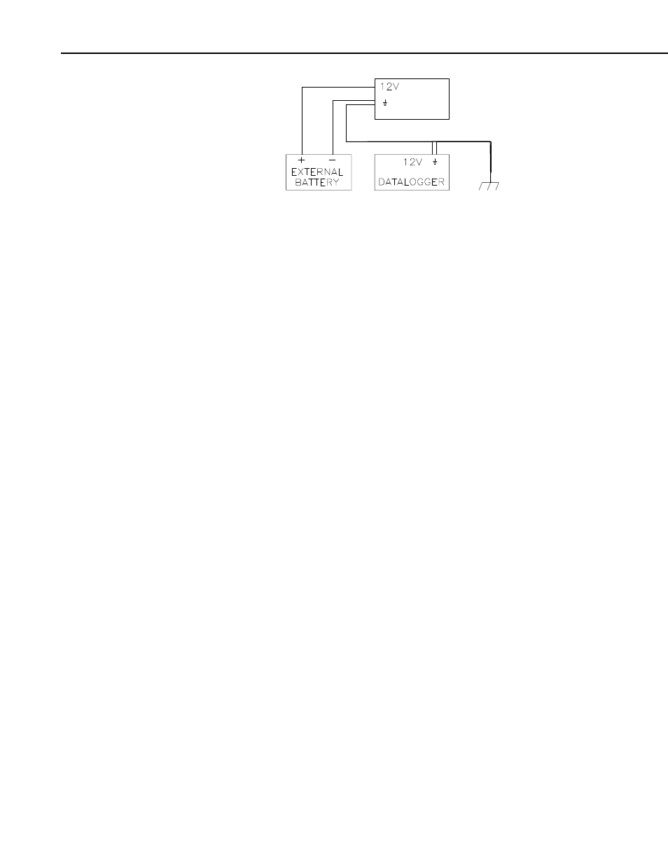
FIGURE 2. External Battery Connections
4. Sensor to AM25T Wiring
This section and the examples describe differential voltage measurements of
thermocouples. It is possible to make single-ended measurements with the
AM25T, however they are more likely to have problems (Appendix A).
Shield wires are connected to the ground terminal next to the measurement
channel and left unattached at the sensor.
4.1 Thermocouple Measurement
An internal reference RTD is located in the AM25T. This reference
temperature does not require an additional datalogger input to measure the
reference. The RTD is located in the center of the multiplexer on the strain
relief flange.
Thermal gradients between the AM25T's sensor input terminals and the RTD
cause errors in thermocouple readings. For example, a one degree gradient
between input terminals and the RTD will result in a one degree measurement
error. The central aluminum (strain relief) bar and the cover are designed to
reduce gradients.
Heat conduction along the thermocouple wire, into the terminal strips, can be
reduced by coiling some excess lead wire inside the enclosure.
The datalogger manual contains a thorough discussion on thermocouple
measurements and error analysis. Consult the datalogger manual for more
details.
For a differential voltage measurement of a thermocouple, wire the high side of
the thermocouple to the high side of a differential input channel and the low
side of the thermocouple to the low side of the channel. Thermocouples that
follow the U.S. industry standards use red insulation on the low side of the
thermocouple. Wire one thermocouple per differential input channel
(Figure 3).
6