N l;n – Ashcroft GC52 - Rangeable wet/wet Differential Pressure Transmitter User Manual
Page 5
5
3. To adjust Output Zero Point (4mA) and Output Span Point
(20mA) the unit must be in the functional area as noted below
while adjustment is via $ # keys. The value shown is a percent-
age of the pressure range (span) as noted on the product label
(ex. If product was supplied as a 0-40 IWC range and the user de-
sired the Output Zero Point (4mA) to be “moved” from 0 IWC to 20
IWC then Output Zero Point would be 50.0 which is 50%.
C.
Re-scaling in “Arbitrary” units, “Linear Display Mode.” This function
allows the user to establish a linear relationship from the standard “inH
2
O”
unit to any user defined unit.
Note: See menu schematic on last page. Unit must be in “Linear Display
Mode” option within “Setting Mode”, this is noted on the screen by
Use $ # keys to move between “Linear Display Mode” and “Pressure
Display Mode.”
a 90.0
a 10.0
n non
-
Note: For setting of zero point and span point in the analog
output, input the percent value over the pressure range.
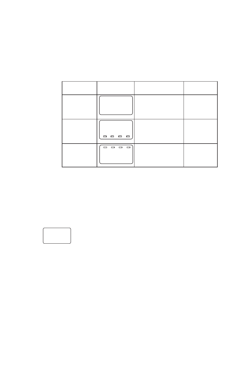
Setting
LCD
Setting
Setting
Item
Display
Description
Range
Display
Selection of
non:pressure
mode
pressure display
display mode
mode : non
Lin: linear
display mode
Output
Analog
Pressure
zero point
output zero point
range:–10
(4mA) : 10.0 (%Span) to 110% Span
.
Output
Analog
Pressure
span point
output span point
range:–10
(20mA) : 90.0 (%Span) to 110% Span
Values shown below are from I&M manual.
n L;n
-