Ashcroft GC52 - Rangeable wet/wet Differential Pressure Transmitter User Manual
Page 12
12
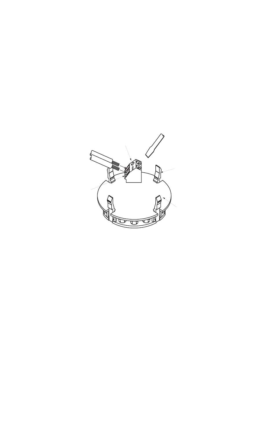
Display
Wire terminals
Wire
Turn with a screwdriver
LCD clips (4)
Display board
Power supply
terminal block
• Remove cover and carefully remove the display to access the terminal strip,
take care not to mishandle the display and associated electronics.
• Turn display over to expose terminal strip, make positive and negative connec-
tions; insert wire equal to the recommended strip length (0.25˝).
• After completing connections, align the retaining clips of the display with the
housing’s notches and carefully place into the housing. Be sure that the inter-
nal sensor ribbon cable does not cross the power supply lines just installed.
• Be sure to properly tighten the sealing grommet when using the Cable Gland
before applying tension to the cable; the cable gland provides strain relief and
environmental sealing.
• Tighten GC52 cover to maintain environmental rating.
• Connect to power source and receiver, than apply power to confirm correct
wiring.
• Power Supply Requirements: Although the 4-20mA signal can travel over long
distances, a very common issue to arise involves inadequate power at the
pressure transmitter – this results in voltage drop across the loop. Be sure to
review the accompanying table to determine whether the 12-36Vdc has been
received at the pressure transmitter.